

Making Rheinberg illumination discs
By Carel Sartory
When, at a Quekett Microscopical Club meeting in 1896, Julius Rheinberg proposed his “Multiple Colour Illumination” as a means of increasing the contrast of unstained specimens, making the discs was not a simple matter; fortunately it is now much easier.
Using colour inkjet or laser printers, overhead projector (OHP) film and free software, making Rheinberg filters is now quite simple. You can experiment with different colour combinations, and as well as enhancing the specimen information available, the results can be aesthetically very pleasing.
The principle behind Rheinberg filters is to illuminate the object in one colour (let’s say red) against a background of a contrasting colour (let’s say blue) thus making details of the object’s structure more obvious because the eye is good at “seeing” the different colours.
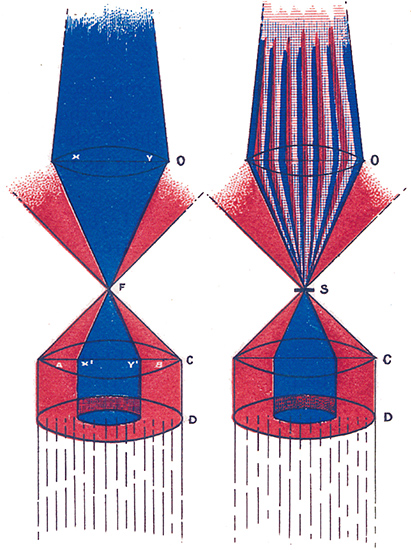 Figure 1. One of Rheinberg’s original drawings illustrating the principle. The left illustration shows that with no specimen, only the blue light enters the objective. The right illustration shows how a specimen interacts with the peripherally-coloured light and so appears red on a blue background.
O=objective; F=focus; S=specimen; C=condenser; D=Rheinberg filter disc
Darkground (darkfield) illumination works in a similar way by excluding all the direct light to show a brightly-illuminated object on a black background.
So what information do you need to know before making Rheinberg filters and darkground stops, and how do you make them?
First you need to know how big the filters need to be and where to put them.
The filters need to go below the microscope condenser near to the plane of the condenser iris or in one that is conjugate with it. Most microscope condensers have a swing-out filter holder just below the iris and this is an ideal place for your dark-ground stops and Rheinberg filters to go.
Make a note of the diameter of any filters you have that fit this holder, or if you have none measure the diameter of the holder itself. Your stops need to drop into the holder and be easily changed. Assuming you will be making them from OHP film they can easily be trimmed if they are slightly too big; if they are too small they will, of course, fall through the filter holder.
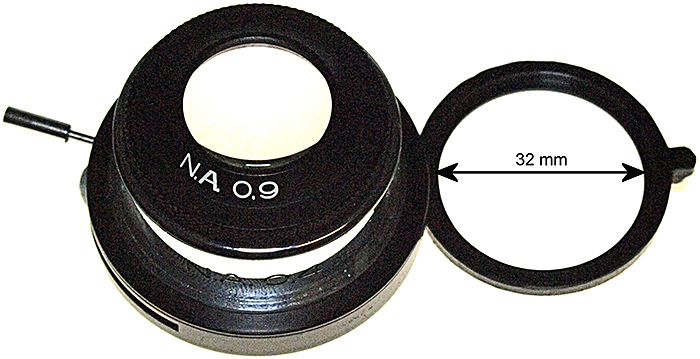 Figure 2. A condenser with a swing-out filter holder suitable for Rheinberg filters and darkground stops.
The next thing you need to know is the size to make the central stop or colour patch; this is a bit more complicated but not difficult. At this point it is worth noting that the techniques discussed here are not really suitable for high-power objectives (above ×40)
Many manufacturers publish information stating the sizes of darkground stops required for various objective/condenser combinations but it is easy to work them out for yourself in any case.
Start off by setting up the microscope for brightfield use with a suitable slide and say the ×10 objective.
The central stop or colour patch needs to be just big enough to cover all the direct light that enters the objective. To find out how big it needs to be, remove an eyepiece and look down the tube at the rear lens of the objective (if you have a phase telescope it makes the job much easier). Whilst looking down the eyepiece tube, open and close the condenser iris. You will see that the circle of light gets bigger and smaller accordingly. Now open it until the image of the iris only just disappears and the objective rear lens is filled with light.
You need to measure this iris diameter quite accurately so remove the condenser without moving the iris leaver, then using a ruler (or better still a pair of drawing dividers) measure the diameter of the iris.
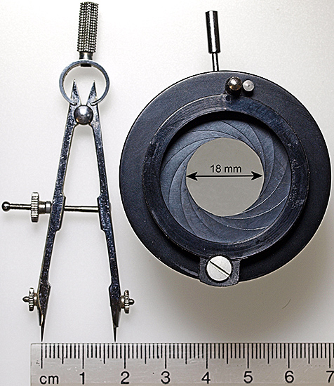 Figure 3. Calculating the size for the central patch; in this case 18 mm.
Replace the condenser and repeat the process with your other objectives (×4, ×5, ×20, ×40 etc.) I recommend you remove the top lens of the condenser for the lower powers (flip it out of the light path if you have a flip-top condenser). Note that lower powers have smaller central patches than higher ones.
You should end up with a set of measurements like this:
Condenser A: Overall filter diameter (to fit the filter holder) 32 mm
| Objective | Central patch diameter with top lens in the light path |
Central patch diameter with top lens removed (flipped out) |
|---|---|---|
| ×5 | 15 mm | 15 mm |
| ×10 | 18 mm | 23 mm |
| ×20 | 18 mm | 26 mm |
| ×40 | 23 mm | not recommended |
So, for condenser A, you need to make 4 sets of stops and filters all with an overall diameter of 32 mm but with central patches of 15 mm, 18 mm, 23 mm and 26 mm.
You will probably need to make different sets of filters for each condenser you use.
You now have all the information you need to make your filters.
They can be created using a computer and photo editing, CAD or illustration software or even with Microsoft Excel or PowerPoint. Essentially the process is the same in all cases; an accurately-sized template is designed and then used to produce the differently coloured filters.
I favour using a free program by Avery Dennison that is intended for designing postage labels. Called DesignPro 5.5 Lite Edition, it is free to download from the company’s website and it makes the production of a selection of different filters on a sheet of A4 OHP transparent film very easy. [DesignPro appears to have been replaced by Avery Design & Print.]
Because the software is intended for label production, it comes with a set of templates for different standard sizes of Avery labels; by using a template for a sheet of 21 labels each 63.5 × 38.1 mm in size for each patch diameter, you can build a set of files for all the various filters and stops you require.
Having loaded your label template, set up the design label screen with 1 mm horizontal and vertical scales and the handy grid of blue dots set 1 mm apart. Use these tools to design your filter template ‘label’.
Ignore the ‘Master’ tab. The filter and patch size is designed on the ‘Label 1’ tab.
Draw a circle the overall size of the filter using the drawing ellipse tool and the rulers and blue dot grid, then using the centre vertically and horizontally commands centre this on the label.
Repeat the process for the patch, setting a wider line thickness around it (0.7 to 1.0 mm thick). You now have a template with two correctly sized circles centred on the label
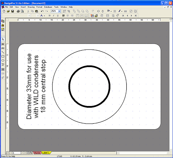 Figure 4. A template for a set of filters ready to be copied as new label tabs.
I also include a text box to remind me what the circle diameters are and which condenser they are for, but this is not essential.
Next use the copy tab command to make as many copies of the label as you require, up to 20 more for one A4 transparency sheet
The dimensions and line thicknesses are now set for all the labels on the sheet, but you are able to vary the colour of the patch and peripheral area for each label.
Move to label 2 and first set the periphery colour by right-clicking on the outer circle and selecting ‘fill colour’ from the drop-down menu; choose an appropriate colour, let’s say yellow. Repeat the process for the inner patch circle and choose a contrasting colour, let’s say blue.
Move to label 3 and ignoring the periphery, fill the inner patch circle with the same colour as label 2 (blue in this case). You now have your first Rheinberg filter ready to print and cut out.
Repeat the process for the rest of the sheet, choosing appropriate colours for the rest of the labels.
To make darkground stops just choose black as the patch colour with a clear, uncoloured periphery.
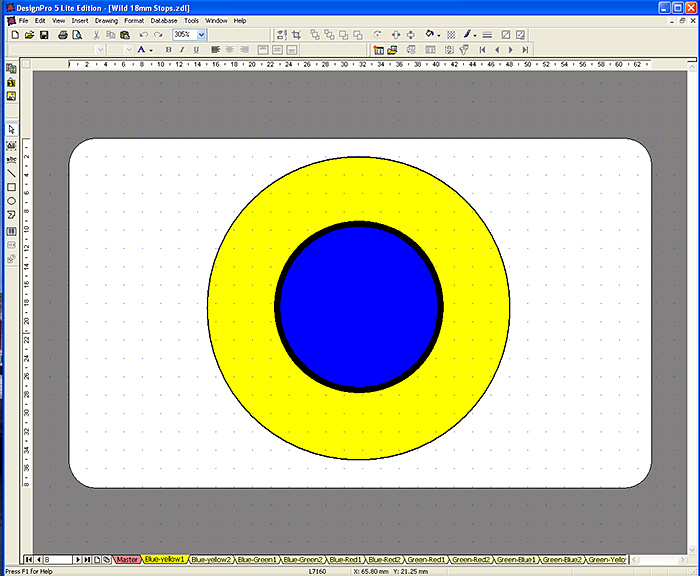 Figure 5. A finished template: First fill in the peripheral colour, in this case yellow, and then the patch colour, in this case blue. Note that this will be paired with a label that has a clear periphery and a blue patch to make one Rheinberg filter.
Experience shows that blue and green are the best colours for the central patch and that red, yellow and clear are the best for the periphery. Experiment and choose whatever colours you find effective and pleasing.
You can now print out a full A4 sheet of labels.
Clear printable A4 OHP sheets can be purchased at most office suppliers or via the web. It is important to buy high-quality absolutely clear sheets, however, don’t be tempted to save money by buying cheap ones, they are not truly transparent and have a mottled surface on the printable side so are not suitable for use as filters.
Set your colour printer to print transparencies at high quality and print off your sheet of labels. Handle the OHP sheet carefully to avoid leaving fingerprints and smudges on the print surface.
Now comes the DIY bit: For each Rheinberg filter ‘label’ you have also made a second one with only the centre patch coloured and with a clear periphery. You now need to cut up the transparency into pairs of such labels and then carefully stick them together print side to print side.
There are two reasons for doing this; 1, as stated above the print side is easily smudged but the other side is not, it can be easily cleaned with a soft cloth and 2, by doubling up the central patch you increase its density, so that the object, lit by the peripheral colour, is brighter than the background colour.
The two labels have to be carefully aligned but with a little practice this is easily achieved. Breathing on the two print surfaces just before pressing them together allows the ink to act as an effective cement.
Using fine scissors you can now cut out your completed Rheinberg filters and stops.
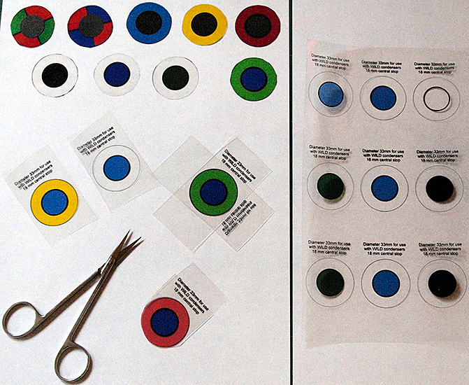 Figure 6. Assembling the Rheinberg filters: The filters are cut from the sheet in pairs, stuck together print face to print face and then cut to size with fine scissors. To the right is part of an uncut A4 transparency, at the top left are various completed filters, below them is a pair of blue/yellow ‘labels’ ready to be stuck together to make a blue/yellow filter and a blue/green filter ready for cutting out. The blue/red filter is in the process of being cut to size.
Any unstained specimens are worth trying your Rheinberg filters out on; I find blue or green central patches with clear peripheries are the ones I use most. The natural colours in thicker specimens show well [fig 8] and thinner specimens are white on a coloured background [fig 9]. A blue centre with a yellow or green periphery also produces pleasant results [figs 10 & 11]
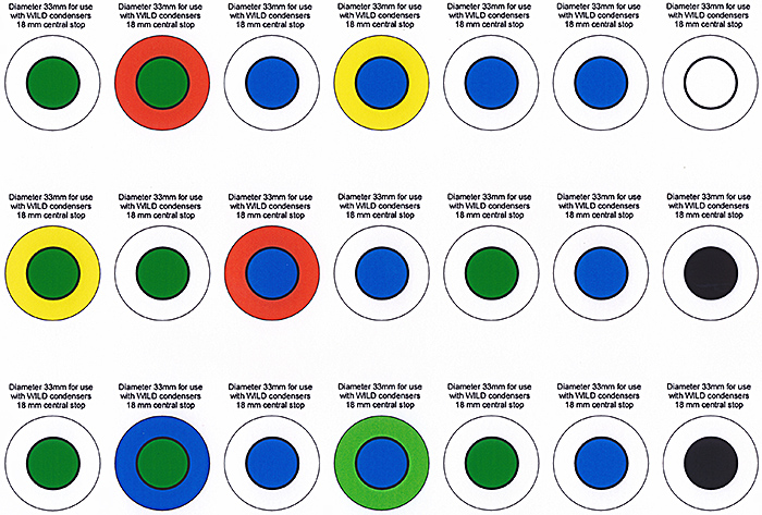
Figure 7. An A4 sheet of filters ready to be cut out and assembled. Note that each filter is made up of two labels, one of which has a clear periphery; they are cemented together to make one filter. The two labels lower right have solid black patches to make a darkground stop.
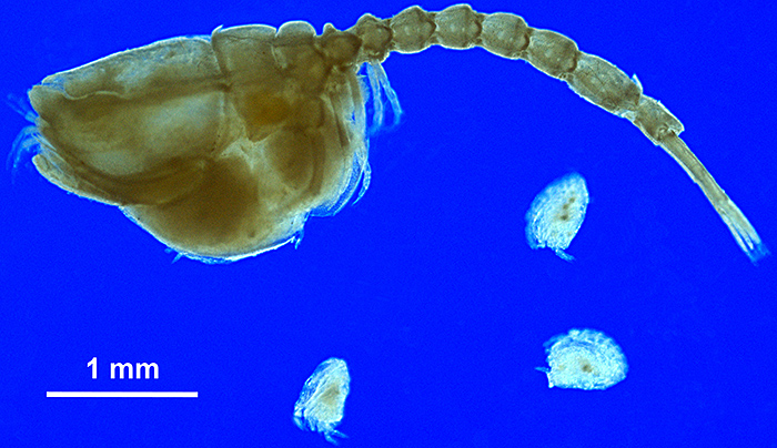 Figure 8. A Cumacean, Bodotria scorpioides with newly-liberated young. Blue patch with a clear periphery.
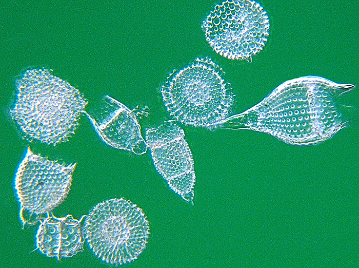 Figure 9. A 20-image stack of Radiolaria using a filter with a green patch and a clear periphery.
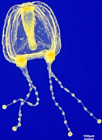 Figure 10. A 22-image stack of a medusa, Coryne eximia. A blue patch with a yellow periphery.
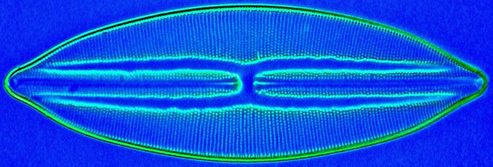 Figure 11. A diatom, Lyrella lyroides (Navicula lyra). A blue patch with a green periphery.
Rheinberg also recommended other types of filters, notable amongst them are quadrant filters, two of which are shown at the top left of fig 6.
Illuminating some objects that have regular structures, using a filter with pairs of opposite quadrants in contrasting colours, and a central patch of a third colour or a black stop produces an interesting effect. When the filter is oriented correctly structures at right angles to each other are shown in the contrasting colours.
For instance, in fabrics, the warp is shown in one colour and the weft in another, either on a background the colour of the patch or on a darkground if a black stop is used.
The filters are a bit more difficult to design, since four squares with corners meeting in the centre of the filter have to be added to the filter template ‘label’. They are then filled with colours in a similar way to the periphery of your other filters.
Try quadrant filters with unstained wood sections, woven fabrics and synthetic meshes like net curtains.
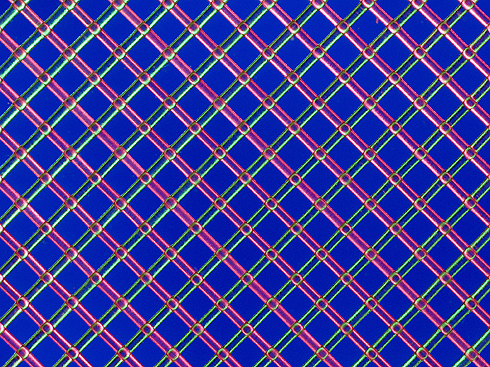 Figure 12. Polyester mesh illuminated through a red/green quadrant filter with a blue central patch.
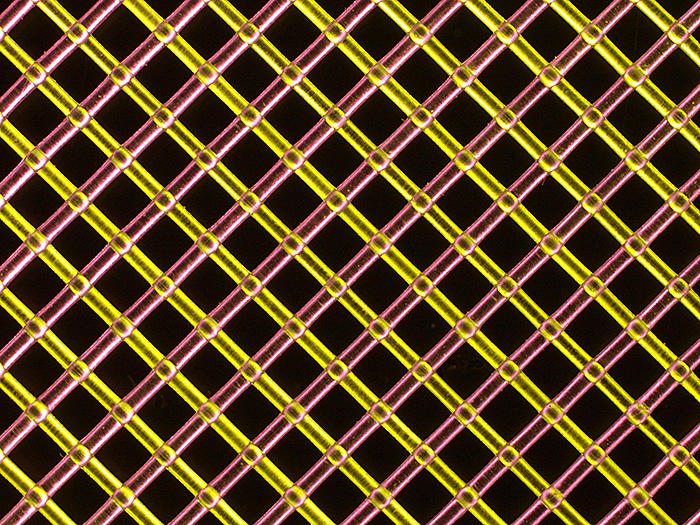 Figure 13. The same polyester mesh illuminated through a yellow/red quadrant filter with a black central stop.
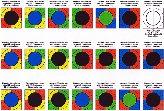 Figure 14. An A4 sheet of quadrant filters ready to be cut out and assembled.
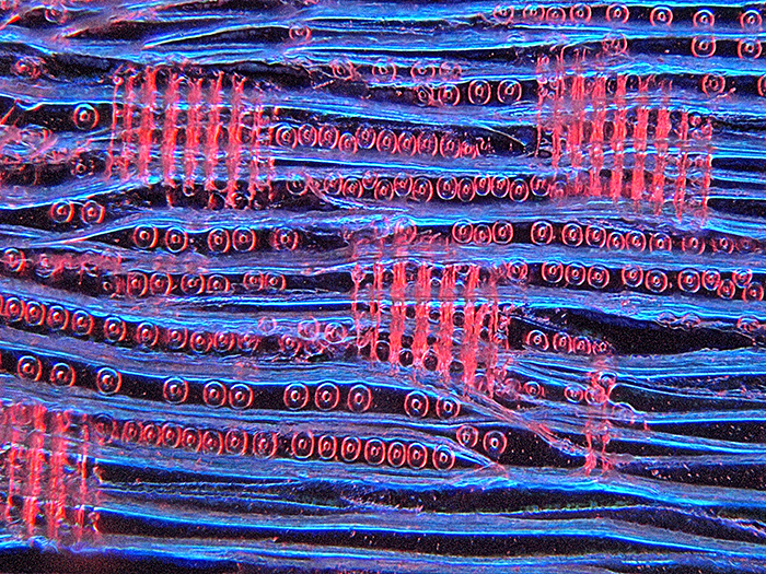 Figure 15. Dry-mounted thin section of deal, Pinus sylvestris, illuminated through a blue/red quadrant filter with a black central stop.
February 2013