

9. Image recording
Image recording – an outline: drawing, cameras, exposure
The images that we see with our eyes are transient. This is so whether we use the naked eye alone or an optical aid such as the microscope. To keep any form of permanent archive of the image, we must record it in one form or another. To not do so necessitates setting up the microscope repeatedly, with the same object under the same conditions: all too often, the original object may not be available. Additionally, a record of the image, once captured, may be referred to frequently or duplicated and transmitted to others, as desired.
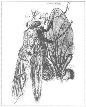 The earliest form of image recording was by drawing and engraving. In these times of increased technological sophistication, drawing is all too often disregarded, but it has its own unique properties to commend it, and many of the engravings found in the earliest works of microscopy are exquisitely beautiful. Figure 1, for example, is copied from Hooke’s Micrographia from 1665. With the advent of photography in the 1860’s and the introduction of artificial illuminants, photomicrography developed in sophistication, and came to occupy an important niche in microscopy. In the closing decade of the twentieth century, with the wide availability and relatively low cost of powerful home computers, sophisticated software packages, and analogue-to-digital converters such as video cameras and scanners, digital image recording and manipulation is as valuable as the other methods available to the microscopist.
Drawing
The subject of recording the microscopical image by drawing and other means has been dealt with by Savile Bradbury in his Presidential Address to the Quekett Microscopical Club (Bradbury, 1994), as well as by Rost & Oldfield (1999) or Brodie (2003). The simplest way to draw the image is to use a net graticule in the eyepiece and transfer an impression of the image step-by-step onto a sheet of paper on which a grid of squares has been very lightly drawn. Otherwise, the microscope can (with a sufficiently powerful illuminant, of 100 Watts output, or more) be arranged to project the image onto a wall, or with a prism onto the bench, from which it can be traced onto a piece of paper.
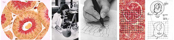
Figure 1. (a) – (e) left to right
(a) Coloured drawing for book plate, from the middle of the 19th century (b) Drawing tube in use; adjust the lighting over the drawing pad and image (c) Drawing over outline in ink (d) Net graticule over image (e) Net graticule in use.
It is easier however to use a camera lucida or its modern successor, a drawing tube, to achieve the same means. These pieces of apparatus (for illustrations, see Bradbury, 1994; Bracegirdle & Bradbury, 1995) permit the simultaneous observation of the image and the paper. The main difficulty when using a camera lucida is to balance the relative intensities of the microscope illumination versus that lighting the paper, for which an Anglepoise lamp is useful. First use a sharp pencil to record the outline faintly, then complete the outline and detail with drawing pens. The majority of fine detail is added by freehand. At all costs, avoid adding detail in ‘sketch’ form. Be aware, too, of the degree of reduction made by any printer for publication. The limit of human visual acuity is 0.1 mm. If the drawing is to be reduced by a factor of 5, then no fine detail drawn smaller than (5 x 0.1) 0.5 mm will be visible in the final print. This will limit the amount of fine detail needed to be included in the drawing.
The principal advantage of drawing is that the attributes of several specimens can be combined into one hand-drawn illustration, a versatility excluded from photomicrography. Information from different focal planes in the image can be incorporated into one drawing. By the same token, a selective impression can be recorded, and extraneous or confusing detail omitted. As in photography, there are subjects which inevitably record less well than seen with the (adaptive) human eye. Under these circumstances, a top-quality drawing is a much better option.
Set against these advantages are the disadvantages: it is time-consuming, so only static objects can reasonably be recorded, care is needed to produce an accurate drawing, and subjective bias should be avoided. Drawings generally require colour to be added freehand afterwards, and in this respect colour film is much more objective and accurate at recording the image. Finally, it is possible to combine the advantage of accuracy offered via photomicrography with the selectivity of drawing by drawing in ink over a faint photographic print. Further practical details are given in Bracegirdle & Bradbury (1995) and Rost & Oldfield (1999).
Photomicrography
The distinction between photography, photomicrography and photomicrography lies in the reproduction ratio and the lens system used to form the image. The reproduction ratio is that between the object and the image on the negative. Although there is some overlap between the disciplines, there being no distinct cut-off at particular reproduction ratios, the following explanation might help to distinguish the differing terminology in use.
General photography uses ratios from 1:1 to 1:infinity. The closest a standard 50 mm lens can focus is ½ metre, giving a maximum ratio for photography of 1:10 (where the image of the object on the sensor is 1/10th of its actual size). Close-up photography ranges from 1:1 to 1:20 (1/20 magnification) and macrophotography, as an extension of this, by photographic enlargement, from 1:1 to 20:1 (20× magnification). Reproduction ratios greater than 10:1 magnification require specialized equipment. If a single lens is used the process is photomacrography. The lenses are designed for use without an eyepiece (e.g. Zeiss ‘Luminar’, Leitz ‘Photar’, Nikon ‘Macro-Nikkor’, Olympus ‘Macro Zuiko’) on extension tubes or bellows, at reproduction ratios from 10:1 to 50:1, say. Readers are referred to Bracegirdle (1994) for a definitive treatise on the subject.
Photomicrography requires a compound microscope, with objective used with an eyepiece, and is the correct term for recording an image seen down the eyepiece, or on the monitor, with reproduction ratios from 10:1 to an upper limit around 2,000:1 (where the image of the object on sensor is 2,000× its actual size). Beyond that is the province of electron micrography. Microphotography, on the other hand, involves the production of minute photographs: it uses reversed objectives to form the image by reduction, with reproduction ratios from 1:10 to 1:200, or less. It is a reduction method, requiring a microscope to magnify and thus observe the image.
The remainder of this article discusses the equipment needed for photomicrography. Brief comments are included about calibrating equipment to determine proper exposure, the type of film stock to use, and the handling of colour film. However, to cover these considerations in detail would merit another article beyond the scope of this introductory series. For an account of photomicrography with suitable practical schedules, see Evennett (1989). Another reference work, already quoted, is Bracegirdle & Bradbury (1995). Neither is there space here to consider image recording using a video camera. Several practical articles have been written by Quekett Microscopical Club members, e.g. see the articles written in Microscopy Bulletins Nos. 17 & 29, and that by Dodge, Dodge & Jones (1988). Using analogue video cameras to capture images is largely being displaced by the affordable introduction of digital cameras incorporating CCD sensors.
Equipment and films for photomicrography
It is possible to record a microscopical image onto film, without a camera, by setting up the microscope to project the image, as one might do when drawing. For further details, see Bracegirdle (1993). Several types of camera, in different formats may be attached to the microscope: proprietary 5″ × 4″ and 120 roll-film camera backs are manufactured, but most routine photomicrography has been carried out using 35 mm film for many years. This format has much to commend it; it is relatively cheap to use, and film stock is widely available as either monochrome or colour emulsions of different types.
In the microscope, rays from the eyepiece form a virtual image (see part 2 of this series). The eye converges these rays to form a real image on the retina (a real image is one that can be focused onto a screen). When used for photomicrography, the optical system of the microscope must be modified so that a real image is formed on the film without the eye. This can either be done with a normal eyepiece or a photographic ‘eyepiece’, which is not strictly an eyepiece at all, but a specially-designed projection lens.
The simplest way to form a real image at the film plane is to refocus the microscope so that the primary image falls below the focal plane of the eyepiece, and the upper eye lens of the eyepiece focuses the now convergent rays in the film plane. This is not an ideal situation, particularly with high-power objectives of high numerical aperture, for residual spherical aberration will seriously degrade the image. It is suitable only where the overall extension from the eyepiece to the film plane is large, and/or the numerical aperture of the objective used is low. The advantage of this method is obvious: no additional equipment is needed. A better option, which avoids refocusing the objective (and so retains the proper conjugate distance between specimen and primary image), is to raise the eyepiece in its tube and secure it in place using a piece of adhesive tape or collar of some sort. The best solution of all is to use a custom photographic projection lens in place of the eyepiece, but some equally good systems exist where a specially computed correction lens is used above the eyepiece to form a real image on the film without disturbing the conjugate distances between the specimen and the primary image plane. This last situation is optically similar to using the eye to form an image. Ray diagram illustrations of these arrangements, from Evennett (1989) and Bracegirdle & Bradbury (1995) are shown below.
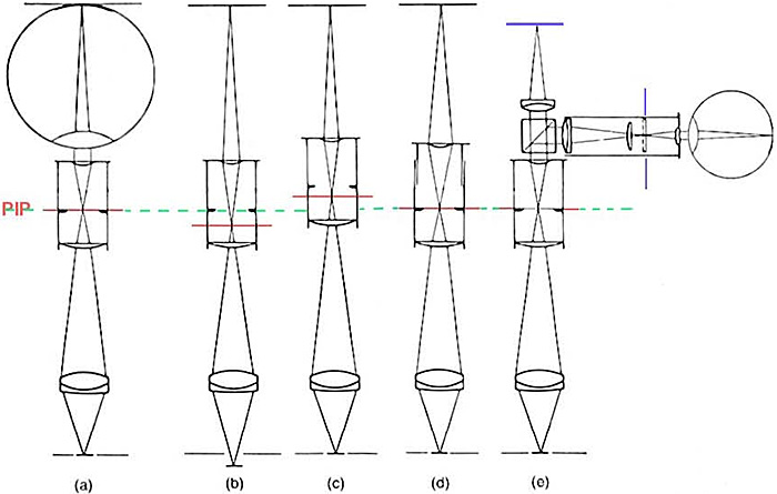
Figure 2. Producing a real image on film.
Adapted from: Evennett (1989), Fig. 2, p. 65. and Bracegirdle & Bradbury (1995), Fig. 2.15, p. 31.
2(a) Our eye focuses the parallel rays leaving the eyepiece, since the primary image (red line) falls in the focal plane of the eyepiece.
2(b) If the primary image is lowered by refocusing the microscope, rays leaving the eyepiece will now converge and form a real image. This method may well produce an imperfect image, since the conjugate distance between the object and objective lens is longer, and the conjugate distance between objective lens and primary image is shorter than those for which spherical aberration was minimised in the design of the objective.
2(c) The eyepiece is raised to increase primary image to eyelens distance, and thus form a real image. The specimen and primary image remain in their correct positions.
2(d) Projective ‘photographic’ eyepiece with variable field/eyelens distance.
2(e) A normal eyepiece with photomicrographic camera attachment and built-in projection lens. The focusing eyepiece is conjugate with the film plane (blue), therefore when the specimen is focused correctly with this eyepiece, it is in focus at the film plane. This is the optical equivalent to using the eye in (a).
In the simplest arrangement, a 35 mm camera without its lens can be attached to the microscope as a camera back via a connecting tube. The bottom of the tube fits around the eyepiece (Figure 3A), and the extension of the connecting tube defines the reproduction ratio. Focusing is done through the viewfinder, and through-the-lens (TTL) metering, if present, will simplify determination of the correct exposure once you have calibrated the equipment. Calibration is discussed further on in this article. Also shown in Figure 3A is a proprietary connecting tube from Olympus, with provision for inserting a projection eyepiece into the optical train. Some manufacturers, e.g. Nikon, use a single correcting lens, within the connecting tube. Others rely on using the normal eyepiece to form a real image, or place their correction lens within the shutter/camera back assembly. Therefore be aware that some connecting tubes are meant to have lenses built-in or otherwise inserted by the microscopist, whereas other designs are merely open and contain nothing more than air!
A more sophisticated photomicrographic assembly is shown in Figure 3B and 3C; in this case it is Zeiss equipment, but a similar arrangement from Olympus is shown in Figure 2 in part 1 of this series. Between the microscope and the dedicated camera back is an automatic electronic shutter. This prevents blurring in the image which can result from the camera shake caused by the focal plane shutter and mirror of some SLRs. A right-angled eyepiece, containing a focusing graticule conjugate with the film plane, is provided to deliver a much brighter image than that seen through the viewfinder of the SLR. Figure 3B shows an exposure meter of the microscope (in this case the Leitz ‘Microsix’) whose sensor is designed to be inserted into an eyepiece port.
Figure 3C shows a dedicated automatic exposure meter: the photocell is built into the slider just behind the right-angled focusing eyepiece. The film format and film speed is set on the control box shown on the left of the microscope base. When using the right-angled focusing eyepiece in this configuration, it may be helpful if the eyepieces are removed and the ports capped off. It is easy for condensation from your breath to form on the surface of the one or both of the eyelenses when attempting to compose and focus the image using the right-angled eyepiece. Other designs dispense with a separate focusing eyepiece, and house the focusing graticule in one of the viewing eyepieces.
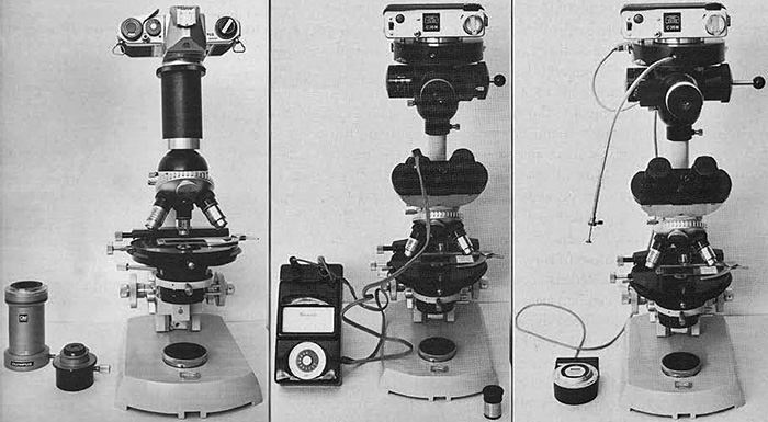
Figure 3. (3A, 3B & 3C; left to right )
3(A) Camera mounted onto a microscope with a simple connecting tube. A right-angled magnifier attached to the camera viewfinder will aid in focusing. 3(B) and 3(C) Systems with built-in viewfinders and exposure meters.
Exposure, calibration and focusing
The human eye can detect small changes in light intensity at the moment they occur, but it is unable to make an accurate quantitative assessment of light intensity. We must therefore rely upon photo-electric cells (which do respond to a given light intensity and any change very accurately) to determine the exposure that must be given to the film. Exposure meters are built around one of three types of photo-cell: selenium cells, cadmium sulphide (CdS) photo-resistors and silicon photo-diodes. Selenium cells do not require an independent battery, which is an advantage, but at low light levels are less accurate than the other two types of meter. The Leitz ‘Microsix’ meter with the eyepiece probe, in Figure 3B, is of this type. Cadmium sulphide cells are very accurate, but require a battery, and can suffer from a memory effect of any previous reading in bright light, which can lead to under-exposure, unless they are allowed to equilibrate before a reading is taken. The Zeiss ‘CS-Matic’ exposure, Figure 3C, is a CdS exposure meter; the battery fits into the rear of the control box. The most accurate exposure meters use silicon photo-diodes; the only caveat is that these meters require an amplifier in their circuitry, and so can be a heavy drain on battery power. Exposure meters are designed to give to correct exposure with ‘average’ subjects. This may suit a well-stained histological section covering most or all of the field of view, but a specimen which does not fill the field of view, or otherwise allows a lot of light through, will be under-exposed, while a subject viewed by dark-ground or fluorescence microscopy is likely to be over-exposed if an integrating exposure metering system is used without any further correction of the indicated exposure. Regardless of the type of meter employed, the microscope and camera have to be calibrated for whichever film is selected.
If a set-up such as that in Figure 3A is used, focusing may be carried out using the viewfinder, but the image may well be dim, and it will not be possible to use any split-screen rangefinder. Where the focusing screen can be changed (as with the Olympus OM-series cameras) a clear screen with focusing cross hairs should be used. It is essential to use an adjustable accessory magnifier to fix the plane of focus of the eyes onto the cross-lines on the screen. Those systems seen in Figure 3B and 3C, use a right-angled adjustable focusing eyepiece, with the focusing screen and reference graticule in the eyepiece. The position of the graticule is designed to be parfocal with the film plane [figure 2(e)].
For accurate focusing on a clear screen, first defocus the microscope image onto a clear area of the slide, and adjust the focusing graticule so that it is sharp. Then bring the specimen into the field of view and focus it. This is easier with high numerical aperture objectives with a more restricted field of view and low depth of field, than low power objectives, of small aperture, with a very large depth of field, but shallow depth of focus. For objectives with a small depth of focus, it helps to use an auxiliary magnifier on the right-angled eyepiece.
The definition of depth of field and focus is as follows: depth of field is the depth of space, about the optical axis, on both sides of the object plane within which the object can be moved and still remain acceptably sharp in the image. Depth of focus is the axial depth of the space on both sides of the image plane within which the image appears acceptably sharp whilst the positions of the object plane and the objective are maintained. For further instruction on this important point – for who wishes to capture out-of-focus micrographs? – see Evennett (1996).
It is best to standardize on one monochrome film, and one colour film in each case, to calibrate your equipment to the exposure characteristics of each combination of film and developer. Kodak’s Technical Pan has the highest resolving power of any film; used properly it gives sharp images, with fine grain, and the contrast may be varied to suit the subject. Most microscopical images do not exhibit high contrast, and so Kodak HC-110 developer is recommended for use with Technical Pan, unless a very high contrast is required. For further practical details see Bracegirdle (1994). With colour film, it is best to use positive (reversal) slide film (with names ending in –chrome) rather than negative film (with names ending in –color) from which prints are routinely made. This is because colour filters are used to print from negatives and this process by its nature can be variable. Conversely, with positive transparency film, it is the film itself that has been exposed in the camera which is used to project an image from the slide. For a more detailed explanation, see Evennett (1995, 1997).
In photomicrography the exposure reading is taken from the evenly-illuminated background without any subject. The background is read because the number of tones in a microscopical specimen is quite limited and therefore, unlike general photography, well within the recording capabilities of the film used. Once the film/developer combination has been selected, a series of seven exposures should be taken at half-stop intervals above and below the nominal speed of the film used. This is done to calibrate the microscope/camera system for the film in use. If there is an exposure compensation dial on the camera, use this to vary the exposure in three steps either way. Otherwise alter the film speed (e.g. if the nominal film speed is ISO 100, use steps of 12, 25, 50, 100, 200, 400, 800. From a properly-developed test strip, the correctly exposed negative which prints well, or the transparency which projects well, can be used to set both the optimum film speed and the correct exposure. The blank background which was measured should print or project so that it is only just slightly darker than pure white. For a thorough calibration, and to cross-check your results, use a different objective, or different lamp setting. The answer should be the same. For a more detailed explanation of this procedure, see Bracegirdle & Bradbury (1995).
Controlling the illumination
The eye is much more tolerant of differences in the intensity of the illumination across the field of view than film. It is therefore crucial that the microscope is properly set up for Köhler illumination, as explained in part 3 of this series. Köhler illumination was originally developed to provide a uniformly illuminated field of view from lamp filaments which would otherwise cause uneven illumination. Some microscopes have a diffuser of finely-ground glass as an alternative means of preventing the appearance of the filament in the specimen and image planes. These diffusers detract from the final quality of the image, and are generally only useful when very low power objectives (×4 magnification or less) with a low numerical aperture and large depth of field are used. Under these particular circumstances, it is possible to include a trace of the unfocused filament image superimposed in the final image even when the microscope is properly adjusted for Köhler illumination.
Unlike a general photographic camera lens, the photomicrographic camera is no more than a camera back. There is no diaphragm for controlling the intensity of illumination – these are part of the microscope system, and are used to control the optical quality of the image and not its intensity. When using monochrome film, it is permissible to use the rheostat on the lamp to control the intensity of illumination for the purposes of making a correct exposure. However white light is composed of different colours across the visible spectrum. Intensely hot illuminants (such as the sun) possess a greater proportion of blue light than cooler sources (e.g. a candle flame or tungsten light) which possess more red wavelengths in their characteristic spectrum. This property is known as colour temperature, and values are expressed in degrees Kelvin (°K).
Our eye-brain system is adept at compensating for differences in the colour of ambient light: this page is perceived as ‘white’ whether it is examined by daylight, electric light or candle light. Colour films cannot compensate in the same manner, and are therefore manufactured with the colour rendering balanced for a particular colour temperature. Daylight film is balanced for 5500ºK, and tungsten film at 3200 or 3400°K for tungsten-halogen lamps and photoflood lamps respectively. For microscopy use the 3200°K balanced film; a detailed scale of the colour temperature of various lamps will be found in Bracegirdle & Bradbury (1995), page 65. Since many microscope lamps do not readily conform to these values, and the colour temperature will change as the bulb ages, or it may be convenient to use a more-readily available daylight balanced film the use of colour correction filters is necessary. The table gives the figures for the Kodak ‘Wratten’ range of filters; most other manufacturers standardise on these numbers too.
| Colour temperature of light source °K | Colour temperature balance of film | |||
| 3200 | 3400 | 5500 | ||
| 2900 | Tungsten lamp at rated voltage | 82B | 82C + 82 | 80A + 82B 2B |
| 3200 | Tungsten-halogen lamp at rated voltage | None | 82A | 80A |
| 3400 | Photoflood lamp | 81A | None | 80B |
| 5500 | Daylight (average) | 85B | 85 | None |
| 6000 | Electronic flash | 85B + 81A | 85B | 81A |
Because the colour temperature of the microscope lamp is determined by the supply voltage, it is not possible, when using colour film, to control the intensity of the light using the rheostat on the transformer. In this case, neutral density filters should be inserted in the illumination path (preferably between the lamp and the condenser) to control the intensity of the light without altering the correct proportion of blue and red light. Some exposure meters can be fitted with additional equipment to measure colour temperature. Practical details of how to determine the voltage at which to run the lamp for correct colour temperature may be found in Bradbury (1998) or Evennett (1989).
It is easy to overlook the intensity and type of illumination which is sometimes allowed to reach the eye. Much of the ‘white’ light used contains a high proportion of invisible infra-red wavelengths, which are effectively absorbed by water – this includes the vitreous humour of the eye. It is recommended that an infra-red cut-off filter should always be used in the optical system to protect the eye. For further explanation of this important subject, see Richardson (1997). As mentioned in part 1, nothing is more frustrating than to find that an otherwise perfect image captured on film is ruined by dirt or marks which have gone unnoticed whilst taking the picture. The eye-brain system is quite good at ‘filtering’ these discrepancies out of the field of view. The procedure for detecting dirt is simple: rotate or move each optical surface in turn, working methodically from one end of the instrument to the other.
Digital imaging
In the few years since this series of articles was first published in the Bulletin, digital imaging has developed apace, and so the next article – devoted entirely to explaining the principles of digital imaging – has been included in this introductory series on microscopy. The rate of technological development in the electronics industry is well known, and at some point in the future the resolving power of digital cameras will match the 35 mm format most often used for photomicrography. There are two practical caveats to note: firstly digital formats cannot match the resolving power even of colour film at present. Current two megapixel (2 × 106 pixel) cameras will need to improve to be able to acquire eight megapixels before parity is achieved, so film emulsion will be with us for some time to come. For the highest quality digital image, it is still best to photograph the subject onto transparency film, and then scan this into the computer with a film scanner, such as the Nikon Coolscan III.
Secondly, most digital cameras are made for the domestic market and have no provision for fixing the camera so that it will transfer the primary image of the microscope onto the CCD sensor of the camera. Currently the Nikon Coolpix 950 has a 28 mm female thread on its lens for attaching filters, so it is possible to connect the camera to a microscope either with the proprietary adaptor, or to select a wide-field eyepiece whose entire exit pupil (Ramsden disc) can be projected onto the CCD sensor. Another option is to buy a digital camera, such as the Nikon D-1, which is designed to accept conventional SLR lenses. It is then possible to use an adaptor to attach the camera to the microscope as one would an SLR. The article by Scott (2000) is commended for its technical explanation of the subject.
Finally, however the image is recorded it is strongly recommended that a notebook is kept to avoid forgetting details and falling into error later. For any meaningful evaluation of your photomicrographs, include a scale bar to indicate the size of the subject (see part 5). This is because the eye is poor at objective assessment of absolute measurement, and learns to estimate size from experience of our life-size 3-dimensional environment. Without previous experience, it is not possible to calculate meaningfully the size of 2-dimensional images seen with the microscope. To record the size of an image and/or the width of a field of view, an extra exposure of a micrometer scale bar substituted for the specimen on the microscope stage at the same magnification as the photomicrograph is well worth the trouble of an extra frame of film. The image of the scale bar can be enlarged to the same degree when making the digital scan or final print, or it may be used to calculate the overall magnification of a projected slide. Many digital image analysis programmes, once calibrated, include an automatic scalebar function in their software.
References
Bracegirdle, B. (1993). Beginning with camera and microscope. Quekett Journal of Microscopy. 37: 22–29.
Bracegirdle, B. (1994). Beginning with camera and microscope (2): Choice of films. Quekett Journal of Microscopy. 37: 207–212.
Bracegirdle, B. (1995). Scientific PhotoMACROgraphy. RMS Handbook 31, Bios, Oxford. ISBN 1-872748-49-X.
Bracegirdle, B. & Bradbury, S. (1995). Scientific PhotoMICROgraphy. RMS Handbook 33, Bios, Oxford. 1-85996-090-1.
Bradbury, S. (1994). Recording the image – past and present. Quekett Journal of Microscopy. 37: 281–295.
Bradbury, S. (1998). Lamp voltage and colour temperature. Bulletin of the Quekett Microscopical Club. 31: 9–11.
Brodie, C. (2003). Techniques for drawing botanical subjects under the microscope.
Dodge, A. V., Dodge, S. V. & Jones, K. (1988). An Introduction to Video Recording at the Microscope. Microscopy 36/1: 43–53.
Evennett, P. J. (1989). Image recording. Chapter 3: 61-102 in: Light Microscopy in Biology – a practical approach, Lacey A. J. (ed). IRL Press, Oxford. ISBN 0-19-963037-2.
Evennett, P. J. (1995). Technical hints, tips and queries. Proc. Royal Microscopical Soc. 30/3: 223–224.
Evennett, P. J. (1996). Technical hints, tips and queries. Proc. Royal Microscopical Soc. 31/1: 63–66.
Evennett, P. J. (1997). Technical hints, tips and queries. Proc. Royal Microscopical Soc. 32/3: 203–204.
Groom, N. G. (1986). Micrography – The making of microscopic-sized photographs. Microscopy 35/6: 445–450.
Richardson, T. (1997). Do you, your slides and your CCD camera need sunglasses? Proc. Royal Microscopical Soc. 32/2: 101–105.
Rost, F. & Oldfield, R. (1999). Drawing with a Microscope. Proc. Royal Microscopical Soc. 34/3: 439–442.
Scott, B. (2000). Digital Microscopy Bulletin of the Quekett Microscopical Club. 37: 25–28.
© Jeremy Sanderson, Oxford, 2010