

3. Illumination
Methods of illumination. Köhler illumination for transmitted light and incident light
The most common form of illumination used today, and well-known to the majority of microscopists, is Köhler illumination. Devised about 120 years ago, Köhler’s illumination was based on sound optical principles, and has therefore become universally accepted. It is by no means the only method available to the microscopist. In this article I shall first cover source-focused and Köhler illumination, before proceeding to the alternatives.
Early microscopists used natural light, and subsequently oil or gas lamps which gave a structureless source of illumination. This method is thus called ‘source-focused’ (also ‘critical’ or Nelsonian) illumination. Illustrations of these lamps may be found in the review of illuminators for microscopy written by Davidson (1990) and also in Bracegirdle (1993).
Source-focused illumination merely requires the lamp source to be focused by the condenser into the plane of the specimen. It is essential to restrict the field of view that is lit by closing down the illuminating field diaphragm (IFD) in order to reduce glare arising from stray light. The IFD is found either on the front of the lamp housing, or is built into the front focal plane of the condenser. The image of lamp source sometimes has to be magnified to fill the field of view. It is possible to remove the image of the filament from the field of view by using an opal light bulb, or a fine-grain diffuse glass screen in front of a clear bulb. With the passing of oil-lamps and the advent of the much more reliable and less messy electric lighting, a considerable drawback arose because the structure of the small source lamp filament was conjugate with the specimen plane, and thus was visible. However, as Barron (1965) says: “It should not be forgotten that microscopy – very good microscopy – pre-dates the general distribution of electricity”.
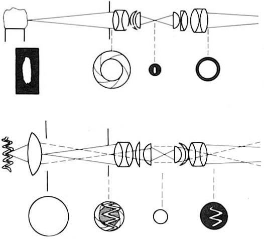
Figure 1. Light distribution in object and aperture planes for source-focused (top) and Köhler illumination (bottom).
Taken from: Hartley G. W. (1979) Hartley’s Microscopy 2nd Edn, Senecio Publishing. Figures. 104 & 105, pages 113, 115.
Köhler arranged to separate the illuminating and imaging rays of the microscope with a bullseye collector lens in between the lamp and the condenser. The two series of conjugate planes are separate but interleaved. The back focal plane of the objective is thus filled evenly filled with light, but the image of the filament, although formed in the remaining planes of its own series, is invisible at the specimen plane which, of course, is conjugate with the retina.
| The series of conjugate planes in Kohler illumination | |
| Illuminating set | Imaging set |
| Lamp filament | |
| Illuminated field diaphragm (IFD) | |
| Front focal plane of condenser (iris) | |
| Specimen | |
| Back focal plane of objective | |
| Primary image plane | |
| Ramsden disk | |
| Retina | |
| (The adjustable iris diaphragm in each set of conjugate planes is highlighted in red) | |
Köhler illumination may used equally well whether transmitted or reflected (incident) illumination is employed. The ray paths are essentially the same, but in epi-illumination the objective acts as its own condenser so that the ray path is ‘folded’ about the axis of the plane mirror reflector. There is no difference in resolving power between source-focused and Köhler illumination when properly set up (Françon, 1961).
Modern microscope stands are built to contain the lamp built into the stand. This obviates the need to align an independent free-standing lamp. If such a lamp is used, it is helpful to manufacture (or acquire) a wooden board on which to mount the lamp and stand in fixed positions relative to one another, so that the amount of adjustment and alignment required each time is kept to a minimum. An illustration, together with construction details for such a board, is shown in Shillaber (1944) pp. 87–88.
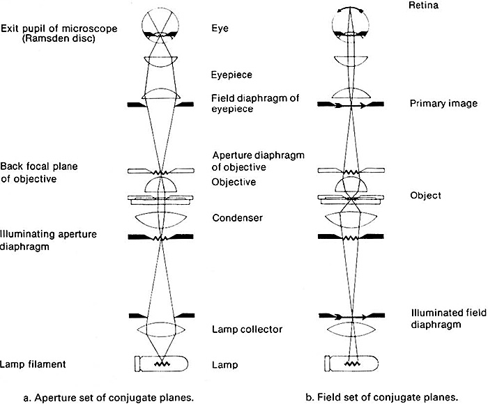
Figure 2. Illustration of ray paths for each set of conjugate planes for Köhler illumination for a transmitted-light microscope. In practice, these ray paths are superimposed upon one another.
Taken from: RMS Dictionary of Light Microscopy, RMS Handbook No. 15, Figures 8 & 9 pages 68, 69; OUP, Oxford.
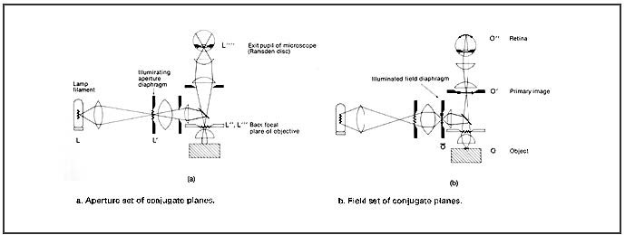
Figure 3. Illustration of ray paths for each set of conjugate planes for Köhler illumination for a reflected-light microscope. In practice, these ray paths are superimposed upon one another.
Taken from: RMS Dictionary of Light Microscopy, RMS Handbook No. 15, Figures 8 & 9 pages 68, 69; OUP, Oxford.
To align the microscope for Köhler illumination on a stand with built-in illumination, proceed as follows: place a well-stained stained specimen on the stage and focus a medium power (×10 magnification) objective onto it. Close down the illuminating field diaphragm (IFD; usually in the base of the microscope) down to a pinhole, and rack the condenser up and down until the image of the iris leaves are in focus at the specimen plane. Open up the IFD to just fill the field of view. Remove an eyepiece and observe the back focal plane of the objective. Adjust the condenser iris (which can now be seen), so that it is open about 80% of the diameter of the circle seen in the back focal plane of the objective. Replace the eyepiece and proceed to use the microscope. More detailed instructions for adjusting a microscope according to Köhler’s principles may be found in Bradbury & Bracegirdle (1998), Evennett (1983) or Sanderson (2002). An explanation of how to adjust the eyepieces properly may be found in Evennett (1996).
Barron (1965, pages 99–101) gives an account of how to set up Köhler illumination on a monocular microscope with an external light source. The external lamp should have an illuminated field diaphragm and condensing lens. Place the lamp horizontally, light it and direct it towards a wall. Focus the filament on the wall, and open the field diaphragm fully. Ensure the colour fringes and flare surrounding the filament image are symmetrical, otherwise centre the filament to the field condenser lens in the lamp. Ensure centration is maintained as the illuminated field diaphragm is closed down. Place the lamp about 8 inches from the mirror. Adjust the microscope mirror, plane side towards the lamp, so that the lamp beam falls across its centre, and focus the filament image sharply. Use a piece of white paper as a screen to make the image visible. Remove the objective, eyepiece and condenser, and white paper screen. Put a piece of tracing paper over the top of the tube, and ensure it is strongly and evenly illuminated. Replace the optical components, and rack up the condenser. Place a temporary tracing paper diffuser in front of the lamp, focus on a specimen and centre the condenser. Remove the diffuser and close the field diaphragm; manipulate the mirror until the image of the field diaphragm is central. Focus the condenser until the image of the field diaphragm is sharp. Open up the field diaphragm to fill the field of view. Look under the substage to check that the filament image falls on the condenser iris. Adjust the condenser iris (as above), so that it is open about 80% of the diameter of the circle seen in the back focal plane of the objective. Replace the eyepiece and proceed to use the microscope.
To align the microscope for source-focused illumination using a mirror stand and independent lamp, proceed as follows: Set up the lamp about 8 inches (20 cm) from the mirror on the microscope stand. Remove all lenses (condenser, objective and eyepiece) and also remove any diffusing screen. Adjust the mirror with the plane side of the mirror uppermost to direct light up the microscope tube. Replace the glassware, place a well-stained specimen on the stage and focus a medium power (×10 magnification) objective onto the specimen. Rack the condenser up and down until the lamp is focused onto the specimen. Centre the lamp to the optical axis either by using the condenser centration controls, or by closing down the illuminated field diaphragm in front of the lamp and tilting the mirror as appropriate. The diaphragm can then be opened until it just fills the field of view. If needs be, the lamp does not need to have an iris diaphragm in front of it. Provided the lamp is fitted with some sort of filter holder, it is possible to construct a series of aperture holes cut out of stiff card. If the diaphragm is non-centrable and/or the opal bulb has no surface markings, inscribe a cross very lightly on the centre of the bulb to aid alignment.
These days the most usual form of electric lamp used is the tungsten lamp ranging from 15 watts as integral illuminators built into the microscope stand, through 30, 50 and 60 Watts to 100 or up to 250 Watts. The voltages of these lamps are either 6 volts or 12 volts direct current stepped down from the 230 volts alternating current supply. An improvement, which reduced blackening of the glass envelope with ageing, came with the introduction of the quartz-iodide (Q.I.) or tungsten-halogen lamp. Iodine vapour, contained within the glass envelope, combines with tungsten evaporated from the electrode onto the glass to form tungsten iodide which, in turn, dissociates at high temperature on contact with the filament to renew the tungsten in the filament and iodine in the lamp.
References
Barron, A. L. E. (1965) Using the Microscope. Chapman & Hall, London.
Bracegirdle, B. (1993) Microscopical Illumination in the 1890s Proc. Royal Microscopical Society, 28/4: 196–201
Bradbury, S. & Bracegirdle, B. (1998) Introduction to Light Microscopy 2nd Edn Bios, Oxford. RMS Handbook No. 42
Davidson, B. M. (1990) Sources of Illumination for the Microscope. Microscopy 36/5: 369–386.
Evennett, P. J. (1983) Köhler Illumination: A simple interpretation Proc. Royal Microscopical Society, 28/4: 189-192
Evennett, P. J. (1996) Technical Hints, Tips and Queries, Proc. Royal Microscopical Society, 31/1: 64–66.
Françon, M. (1961) Progress in Microscopy. Pergamon Press, London.
Sanderson, J. B. (2002) Practical Control of Contrast in the Microscope, Microscopy 39/3: 275–288
Shillaber C. P. (1944) Photomicrography. John Wiley & Sons, New York.
© Jeremy Sanderson, Oxford, 2010