

Practical control of contrast
Practical control of contrast in the microscope
Originally published in Quekett Journal of Microscopy (2002) vol 39: 275–288
Jeremy Sanderson
Summary
This is the second of two papers about contrast. The first paper [1] dealt with the theoretical basis of introducing contrast into the microscopical image. This one discusses the practical issues involved in setting up the microscope and accomplishing some of the different contrast-enhancing methods now available. This paper is limited to the better-known methods, and is concerned primarily with the transmitted-light microscope. Since manipulating image contrast is largely within the control of the microscopist, various means of contrast-enhancement may be combined, and success is really only limited by the user. A number of references are cited for those techniques not covered here.
Adjustment of the microscope
Most scientific instruments are limited in their design by technical restrictions, and simply will not operate unless properly adjusted and cared for. The light microscope is perhaps the most exact, yet also one of the most forgiving, instruments ever devised: it will usually deliver an image of the specimen, however badly adjusted it may be, but the better adjusted and aligned the microscope is initially, the better the image fidelity of the object will be. The extraordinary flexibility of the light microscope, together with the need to produce an accurate image, means the microscope must be set up properly from the outset before carrying out any meaningful work. Adjusting the microscope to produce good contrast-enhancement (in dark ground, for example) is best attempted on an instrument which has been properly aligned in the first place.
Part 1: Source-focused and Köhler illumination
Nowadays we expect the specimen to be illuminated uniformly over the entire field of view. However, prior to the widespread use of electric light, this could be accomplished only by using a cloudy sky as the light source, using the condenser. This simple type of illumination is called ‘source-focused’, ‘critical’ or ‘Nelsonian’ illumination. Use of the edge of an oil lamp flame provides only a band of illumination across the field of view, and is not very intense into the bargain. Electric lamps were introduced into microscopy towards the end of the 19th century, and provided a clean, reliable, intense and immediate source of illumination. However, the electric lamp filament possesses a definite structure which, if imaged onto the specimen by source-focused illumination, will interfere with interpretation of the image. August Köhler devised the method of illumination bearing his name to circumvent this problem. A simple and straightforward interpretation has been published by Evennett [2]. What follows is a practical account of how to set up the microscope for Köhler illumination for bright-field microscopy, providing a basis for re-adjusting the microscope for other methods of contrast enhancement.
1. Turn on the light source and swing in a ×10 objective. This will have sufficient working distance (the clearance between the front of the objective and the slide) not to hit the slide while initial adjustments are being made. Raise the condenser to the top of its travel. Open fully the illuminated field (lamp) diaphragm (IFD) and the illuminating aperture (condenser) diaphragm (IAD).
2. Place a slide on the stage, checking that the coverslip is uppermost – we all forget this at one time or another! Use the coarse focus, to reduce the distance between slide and objective to a minimum, closer than the focal point of the objective. Look side-on at the gap between the objective and slide whilst doing this, to ensure that they do not collide. Now, whilst looking into the eyepiece(s), increase the distance between slide and objective using the coarse focus control, and stop when the image of the specimen comes into focus. Adjust as necessary with the fine focus control. This sets the specimen in correct relation to the objective.
3. The correct height of the condenser must now be set. Raise the condenser up to its limit. Close down the field diaphragm almost to a pinhole. This diaphragm is usually situated in the base of the microscope, underneath the condenser and substage assembly. If the lamp is an external one, the field diaphragm will be the iris built into the lamp at the front, after the lamp collector lens. Rack the condenser down slowly until the image of this diaphragm is sharply in focus at the specimen plane, superimposed upon the image of the object.
4. Open up the field diaphragm until its image is almost reaches the edge of the field of view. Centre the condenser with its adjusting screws, if provided; with an external lamp, move the mirror and/or the lamp. Open the diaphragm further by a small amount until the image of the diaphragm lies just outside the field of view. Do not open it too much, otherwise stray light will reduce contrast in the image. (For contrast enhancement methods such as phase contrast and dark ground, which employ their own annular diaphragms in the condenser, the IFD must be left fully open).
5. The correct height of the condenser has now been set. The condenser iris can now be adjusted so that the aperture of the variable cone of light supplied by the condenser can be correctly matched to the (generally) fixed numerical aperture (NA) of the objective. Remove an eyepiece and look into the microscope body tube to inspect the back focal plane of the objective, which should be seen as a disc of light at the base of the tube.
[In addition to removing an eyepiece, the back focal plane of the objective may be observed by two other means. Insert a phase-contrast centring telescope, or screw a low-power objective to the bottom of the drawtube (if fitted). These methods provide a magnified image of the back focal plane of the objective for inspection. If a magnification changer is included, this often includes a supplementary lens system – a Bertrand lens – for the same purpose. A final method is to place an inverted eyepiece over the exit pupil of the eyepiece to view the Ramsden disc.]
Adjust the condenser aperture diaphragm until the image of this iris is just a little smaller than the diameter of the disc of light (about 80% diameter), which represents the full aperture of the objective. Replace the eyepiece.
In theory, the aperture of the condenser should equal that of the objective. However, in this case stray light refracted from the extreme edges of the objective lens elements would cause an appreciable loss in contrast. It is worse, however, to close down the aperture diaphragm too far: this will cause serious degradation in image quality, and loss of resolving power. This diaphragm is not be used to control brightness in the image; rather, use the rheostat control on the lamp transformer, or (where the intensity of the lamp must remain constant, as for colour photomicrography for example) use neutral density filters.
Closing down the aperture diaphragm from its optimum position will increase contrast, and may sometimes be the only method of introducing sufficient contrast to visualise the image at all, but this contrast is gained at the expense of resolution. The rule that the IAD is set open at approximately 80% of the numerical aperture of the objective is for guidance and good practice; by all means break it if you know what you are doing! However, the image will gradually become a less faithful representation of the object: outlines of all features will appear thickened, and adjacent features merge. Decreasing the aperture of the condenser will also increase its depth of field, and bring into focus dust and other contamination from the surfaces of the specimen preparation normally invisible in the properly adjusted microscope. This maladjustment was illustrated in Figure 2/4 on page 623 of the preceding paper [1].
6. If the microscope is fitted with a binocular head, the eyepieces can now be adjusted for comfortable viewing. One or both eyepiece tubes may have adjustable focusing controls capable of adjusting the tube length of the microscope. If only one eyepiece tube of the binocular has a variable control, set up Köhler illumination with the fixed eyepiece and adjust the variable control for the other eye until the image is in focus while the eyes are relaxed. Try not to close the opposing eye while focusing, nor screw the eyes up, but rather relax them – you should be aiming to ‘look through’ the microscope to infinity. Fatigued eyes result if the eyepieces are not correctly adjusted for relaxed viewing of an image at infinity – which is how the microscope is designed to be used.
If the binocular has two adjustable focusing controls, first focus the microscope using a high magnification objective (forty times; a ‘high-dry’ objective – a non-immersion one with high aperture). Change to the ten times (or preferably a lower magnification objective if it is part of a parfocal set), and focus the eye adjustments separately without refocusing the objective. For those interested, the reasons for this adjustment may be found in Evennett [3].
When changing to another objective of different magnification, this will have a different field of view (requiring a change in the diameter of the illuminated field) or numerical aperture (requiring a different illuminating aperture), and both diaphragms be adjusted. With objectives below ten times, the field of view may not be fully illuminated even with the field diaphragm fully open. In this case, the top lens of the condenser should be either swung out or unscrewed from the condenser assembly. Do not defocus the condenser to enlarge the illuminated area, since uneven illumination and a loss of resolving power and image quality will result. Details of how to set up the microscope for source-focused illumination, or Köhler illumination for transmitted-light microscopy with a remote light source, may be found in Barron [4] chapter five, or Bradbury & Bracegirdle [5] chapter seven.
With reflected-light illumination, the light path is folded upon itself and the objective acts as its own condenser. This simplifies matters, but because the field diaphragm cannot be fitted in the condenser/objective (where it would also restrict the imaging aperture), it is located in the next conjugate plane ‘upstream’, in the normal position of the lamp filament, and the filament is imaged into this plane by an extra lens. Because of this, the relative positions of the condenser aperture iris and the illuminated field diaphragm appear to be reversed: the aperture diaphragm is nearer the lamp source, and the field diaphragm closer to the condenser/objective. With reflected-light, or epi-illumination, it is particularly important to pay attention to restricting the area of the illuminated field to avoid stray light – non image-forming light – which if allowed to intrude into the optical train, will reduce contrast in the image significantly. For a discussion of the influence of stray light on contrast in the microscopical image, see Dodge & White [6].
Part 2: Practical contrast enhancement
Microscopical specimens can be considered under four broad headings:
(A) The specimen is either sufficiently thin to be mounted onto a glass slide and viewed by transmitted-light, or
(B) it has sufficient thickness, reflectivity or particular structure that renders it opaque to light, and must be viewed by reflected-light illumination.
Within each of these groups, two further possibilities exist:
(i) They may have no inherent colouration – and are referred to as ‘unstained’, or
(ii) posses their own inherent or artificially introduced colour – they are ‘stained’.
It is usually obvious which class a specimen belongs in, and how it is best observed. Some specimens will be sufficiently thin or transparent to be viewed by transmitted-light: stained thin sections of histological material, or diatoms, for example. Others will be opaque and require observation by reflected-light to elucidate surface structure. Rocks and metals are examples of this class.
Starting with a thin, transparent, unstained specimen, I would first study it with oblique illumination, dark ground and polarised light. These are the simplest methods to use, requiring little extra equipment. I would then use Rheinberg illumination, phase contrast and differential interference contrast. As mentioned previously, various contrast methods may be combined. Having observed the unstained specimen, consider staining the specimen and viewing it by transmitted-light illumination, with and without coloured filters. The use of coloured filters to alter contrast and visibility in the image was discussed in the first paper. Sometimes there is sufficient material to prepare unstained specimens, as well as others for staining. If this is not so, start by examining the unstained material, and then make a decision whether to stain it, or etch it to show surface relief, to provide further structural information; sometimes it is possible to decolourise the stained thin section. For information on staining and/or decolourising methods see Sanderson [7], and for methods of etching see Haynes [8; web addresses 1 & 2]. Note that most etchants are, by their nature, highly corrosive and pose a high risk to eyes, skin and respiratory tract. Opaque materials (such as rocks) can be ground thinly or, in some cases, lifted off the bulk mass as a ‘peel’, then mounted on a glass slide and viewed by transmitted light. Further details for making rock peels can be found in Adams [9; web addresses 3 & 4].
Stained thin sections are normally mounted in a resinous medium as close as possible to the refractive index of glass, so that the only visible features are those that are coloured by absorption of light. However, employing a medium whose refractive index is different from the specimen will increase contrast without staining. Dry mounts, as well as glycerol, gum media, water and oils of varying refractive index can be used, and will, in each case, cause a different appearance in the image of the specimen.
A table of refractive indices of mountants and immersion media has been published in Sanderson [7]. Some authors refer to a ‘visibility index’ (particularly with reference to studying diatoms) to evaluate which mountant is best to use. The visibility index (VI) is the difference between the refractive index (RI) of the specimen to that of the mountant. For example, diatom silica has an RI of 1.430; mounted in air the VI equals 0.43, whilst in DPX (a widely-used resinous mountant) the VI equals 0.1, and in a proprietary high refractive index mounting media, such as Styrax the VI equals 0.38. Obviously, diatoms are normally mounted dry or else in a mountant such as Styrax or Pleurax, but not in ethanol, where the VI is only 0.002 – the preparation would be invisible to most observers. Pleurax has another advantage: its slight green cast acts as an inbuilt filter to aid resolution of diatom structure.
Oblique illumination
Once Köhler illumination has been adjusted for the microscope, it is possible to alter the illumination in a controlled way to alter the contrast of the image. The simplest is oblique illumination, achieved by inserting crescents, or partial stops (Figure 1), in the filter tray (if the microscope is fitted with one) beneath the condenser [web addresses 5 & 6], or even your finger close to the plane of the illuminating aperture diaphragm. Simple crescents can be made by trial and error, cut out of card. A filter tray partially swung into the light path will act as a stop, as will the turntable of phase annuli slightly turned off-centre to obstruct the condenser aperture. It is easy, on a microscope stand fitted with a mirror, to tilt the illumination to light up the specimen obliquely. Baker [10] preferred this method to using an oblique-light stop below the condenser. The original paper is not widely available, so the essentials of the method are given here.
Set up the microscope using source-focused illumination. Place a small field stop, 4 mm in diameter, in front of a 100-Watt lamp with ‘pearl’ or opal glass, and project an image of the stop into the specimen plane. Use an accurately centred condenser with the condenser iris set wide open. Remove the eyepiece and insert a short cork into the top of the body tube or drawtube. The cork should have a hole about 8 mm bored through it; its purpose is to keep the eye on axis down the body tube of the microscope. Place a pencil point in the centre of the stop and look down the microscope through the hole in the cork. Now focus the condenser upwards until the point of the pencil is seen. At this point the mirror is tilted in its gimbals to move the image of the stop while viewing the spectrum formed by the diffraction pattern of regularly spaced objects, such as finely striated diatoms. The illustration in Figure 1, adapted from the original paper, shows what should be seen. Remove the cork, and replace the eyepiece.
For those stands where the illumination and mirror are fixed within the base of the stand, this method is not possible. Instead, partial stops must be used, as described above; otherwise use an oblique illuminator. This is a condenser fitted with a diaphragm that can be rotated and offset from the optical axis (Figure 1). Another form of oblique illumination worth considering is Strange’s variable asymmetric contrast [11].
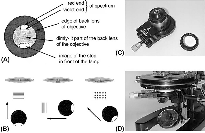
Figure 1. (A) Diagram adapted from Baker [10], showing the appearance of the back focal plane of the objective whilst tilting the mirror to produce oblique illumination.
(B) Diagram showing the azimuth of light in unilateral oblique illumination, and its effect on the appearance and resolution of structure. Structures at 90° to the direction of illumination (from the crescent stop) are resolved, as seen in the lines of striae in the diatom. This diatom, Frustulia rhomboides, is a good specimen for securing resolution of the individual ‘dots’ or punctae with oblique illumination. Arranging the crescent so that it lies at 45° to both the longitudinal and transverse striae will resolve both sets into the individual punctae.
(C) Russian substage illuminator with decentrable iris and exchangeable top lenses. Such a condenser is very useful for providing oblique illumination in a controllable manner.
(D) The illuminator seen in (C) in place. It can be used equally well on a microscope with built-in illumination.
Dark-ground illumination
The diagram published on page 626 in my earlier paper [1] showed the conditions needed for dark ground, namely to exclude the zero-order illuminating beam from directly entering the objective. The numerical aperture of an objective determines the extent to which the objective will accept light; a central stop is therefore placed in the condenser substage filter tray of such diameter that its image in the back focal plane is just greater than the aperture of the objective. This is determined by opening the condenser iris to match the NA of the objective, carefully removing the condenser from its substage mount, and measuring the diameter of the opening of the condenser iris (Figure 2). Virtually any opaque material will do, stiff paper or postcard is ideal: this can be trimmed with scissors. Nail scissors with a curve are suited to cutting small diameters, and this is made easier if the material is scribed with a pair of dividers beforehand.
The closer the dark-ground stop can be placed to the front focal plane of the condenser, where the condenser diaphragm is situated, the better. Watson and many other condensers have their diaphragms at the bottom, immediately above the filter tray, and this is ideal. However, Zeiss condensers have their aperture diaphragms situated at the top of the condenser; the filter tray is carried separately underneath the condenser substage, a considerable distance from the condenser diaphragm. For this reason, the Zeiss microscopes require Zeiss dark-ground condensers rather than a simple central stop.
It is also possible to use an annulus designed for phase contrast as a dark-ground stop. In practice, simple stops for dark ground, or filters for Rheinberg illumination (see below), will only work with objectives up to NA 0.6. Objectives of a higher numerical aperture require a dark-ground condenser of appropriately large aperture. Reflected-light dark-ground illumination normally requires the use of specially designed epi-illuminators, though unilateral dark-ground can be achieved simply by directing light onto the surface of the specimen, from outside the aperture of the objective.
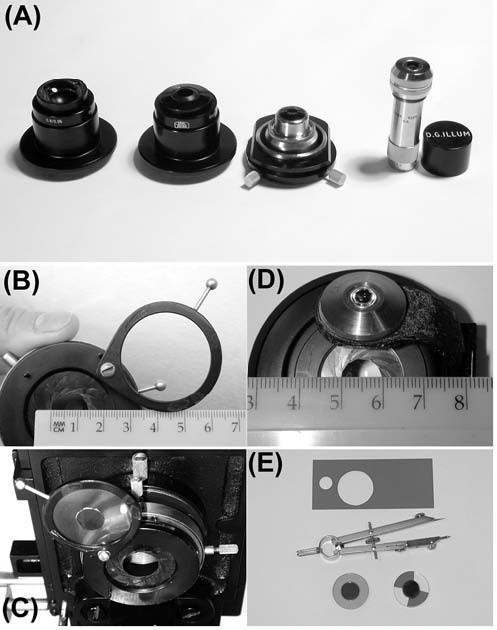
Figure 2. (A) Various types of dark-ground condenser. Left to right: Zeiss dark-ground condenser, with concave top lens [all the others have a flat top surface for oiling to the underside of the slide]; Zeiss immersion; Leitz immersion in a centring mount; Cooke, Troughton & Simms, which may be adjusted, by twisting the top assembly, to accommodate slides of differing thicknesses.
(B) Measuring the diameter of the aperture diaphragm of a Watson condenser, for constructing a dark-ground or Rheinberg illumination stop. Here the opening is 14 mm across, so a stop of 16 mm diameter will work well. The opaque stop is shown mounted on a support disc of transparent plastic, held in the filter tray immediately adjacent to the condenser iris, which is ideal.
The stop is shown in place in (C).
(D) Measuring the diameter of the aperture diaphragm on a Zeiss condenser, where it is situated at the top of the unit, a considerable distance from the filter tray. A home-made dark ground stop cannot work effectively with this type of unit.
(E) Examples of dark-ground (left) and Rheinberg (right) stops. The discs have been cut from the sample swatch of filter material, scribed with dividers, and cut out with nail scissors.
Rheinberg illumination
Rheinberg illumination is a variant of dark-ground illumination. If, instead of an opaque patch-stop, a dark coloured filter is used, surrounded by a larger filter of a lighter colour (usually the complementary colour), the light-scattering features will assume the colour of the larger diameter surrounding filter and the background will be coloured by the smaller central filter. The discs shown (Figure 2) were specially turned from coloured Perspex, but equally effective filters can easily be cut out of coloured Cellophane with scissors, punch or cork borer. Use a disc of transparent material fitted into the condenser substage tray as a support substrate for the coloured filters. Samples can be obtained from theatrical lighting manufacturers such as Lee Filters, whose address is given below. An excellent explanation of making Rheinberg illumination filters has been given by Savile Bradbury [web address 7], and more recently by Carel Sartory.
Rheinberg filters can also be constructed from Polaroid material combined with coloured filters to utilise both colour from polarised light and colour from absorption. This method called ‘Spikeberg’ illumination was developed by ‘Spike’ Walker [12]. This form of contrast enhancement is discussed further by Don Thomson in his page on the Quekett Microscopical Club’s website [web address 8]. A dark-ground stop made from Polaroid material is mounted on a clear plastic substrate (e.g. ‘Ferrero Rocher’ confectionary box). This stop is inserted into the condenser filter tray, with the polar material below, facing the light source, to avoid unwanted birefringence effects of the plastic support. A second polar is placed between the lamp and condenser. By rotating this second (lighting) filter and gradually crossing the polars, it is possible to achieve a smooth transition from brightfield to dark-ground illumination. Setting the condenser diaphragm off-centre will produce a form of oblique illumination, although the effect is better with specially made filters, as described by Strange [11,13] and illustrated also by Trett [14].
Polarised light microscopy
Adapting a microscope for polarised light microscopy is easy. Two pieces of Polaroid material are needed, and these can be purchased as 2″ squares from the Club Shop. Alternatively, a pair of cheap clip-on sunglasses will also provide a source of Polaroid, or filters can be bought from the lighting suppliers already mentioned. The first polar (the polariser) restricts the illumination in one plane-parallel direction beneath the specimen, and a second polar (the analyser) is inserted above the specimen, orientated at 90° to the first, so that no light passes and the field of view is dark overall. The two polars are now said to be ‘crossed’ relative to one another. Conventionally, the polariser is orientated ‘East-West’ and the analyser ‘North-South’, but this is not essential. Depending upon the quality of the optical components and the polars, the field of view may not be entirely dark. The darkest point is easily ascertained by turning one filter relative to the other until maximum darkness of the field of view (extinction) is achieved.
For the highest quality imaging with polarised light, strain-free optics (in particular the condenser and objective) are desirable, but most of us do not have such exotica [with the inscription ‘POL’ or ‘Pol’ engraved in red]. A convenient place to put the polariser is close to the field diaphragm on the base of the microscope, or (better) in the filter tray beneath the condenser. In the case of a cheaper filter, where the optical quality is suspect, it is best not to put the filter close to the field diaphragm on the base of the microscope, since any imperfections will be thrown into the image plane. The analyser can be housed in a slot in the microscope above the objective, otherwise it need be held in nothing more complex than holders fashioned out of black 35 mm film canisters adapted to fit over each eyepiece. For examples these various positions for polariser and analyser, see Figure 3.
Placing apertures and filters in conjugate planes in the illuminating system.
The methods of contrast enhancement described so far involve either preparing the specimen in a particular way, altering the axis of the illumination or inserting filters into the light path. Another way is to insert pairs of apertures and light modulators into conjugate planes at the first focal plane of the condenser and at the back focal plane of the objective. (Here, the term light modulator is used to refer to the special filters inserted into the back focal plane of the objective such as the phase plate, visible as a ring, built into a phase-contrast objective, Figure 4). The three best-known examples are phase contrast, Hoffman modulation contrast and differential interference contrast (DIC). Unfortunately, the back focal planes of most objectives are, in most cases, too small and too inaccessible for the amateur microscopist to work with and insert appropriate modulators for himself. For this reason, phase contrast, modulation contrast and interference contrast equipment is largely custom-made and, for the last two named techniques in particular, not widely available.
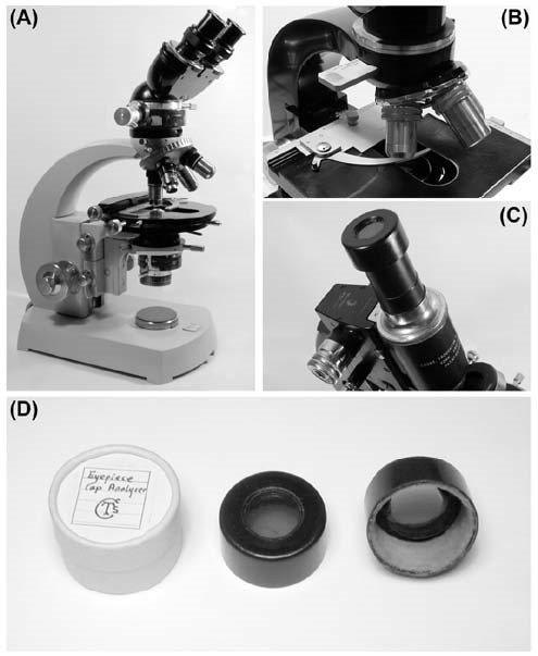
Figure 3. (A) A microscope set-up for use with polarised light. A polariser has been placed over the field diaphragm, on the base of the microscope. [Alternatively, the polariser can be held in a custom-designed unit beneath the condenser substage assembly]. Note, only one or other of these options is used. In between the top of the nosepiece and the binocular head is the unit which carries the analyser. In this case, the analyser can be made to rotate. The circular stage allows the specimen to be rotated at will, without disturbing the arrangement of crossed polars.
(B) A simpler form of non-rotating analyser, held in a captive slot on the microscope stand.
(C) A simply-made eyepiece cap analyser on a monocular CT&S microscope. This unit was kindly made for me by Chris Hammond, whose design it is.
(D) Details of the eyepiece cap analyser. The bottom of a black 35 mm film canister is cut short, and a hole bored through it. A piece of Polaroid is glued over the opening, and the unit is finished with an internal lining of a scrap of velvet cloth for protection and snug fitting.
Phase contrast and differential interference contrast microscopy
Once the microscope has been set up for Köhler illumination with a well-stained slide, replace the stained specimen with the transparent one, without altering the focus. Swing in a low-power (ten times or twenty times) phase contrast objective; initially the specimen will probably not be visible. Insert the correct annulus – usually contained within the condenser housing (Figure 4). A so-called ‘phase-contrast condenser’ will often include multiple annuli, and may also include a central stop for low-power dark ground. Some condensers may also contain Wollaston prisms for DIC. An indication of the appropriate annulus is usually marked on the barrel of the objective in green or black script (e.g. Ph3). If the aperture diaphragm control is not automatically removed from the optical axis when the phase contrast annulus is inserted, open it fully. Check the back focal plane of the objective (see above under source-focused and Köhler illumination). Focus on the phase plate within the objective by altering the length of the barrel of the centring-telescope. Use the annulus-centring adjustments on the condenser to bring the image of the annulus in the condenser coincident with, and superimposed upon, the phase plate of the objective. Note particularly that these centring controls are quite independent of those used to centre the whole condenser to the optical axis: they are either captive on the condenser (usually set at 90° or 120° on the condenser housing) or they may be recessed hexagonal screws at the rear of the condenser, requiring a special key for adjustment. Once adjusted, the annular diaphragms in the condenser should remain centred over a lengthy period; it should not be necessary to readjust each time the microscope is used. Return to viewing the image.
Because the phase contrast technique relies upon the phase ring introducing a quarter-wavelength difference between direct and diffracted beams, a particular wavelength is generally specified. Microscopes operate with light which contains components ranging from 450 nm up to 750 nm, where one quarter of the larger value is not far from half the smaller one. Since the eye is optimally sensitive to green light, and objectives are therefore best corrected for this colour, the wavelength at which phase-contrast objectives are designed to operate is generally 550 nm. For best results, therefore, use a green filter in the illumination path. A ‘halo’ artefact, whereby highly-refractile features in the specimen are surrounded by a bright ring in the image, occurs in phase contrast. For a further discussion of why the halo occurs, see Bradbury and Evennett [15]. Hoffman modulation contrast microscopy also used to enhance the contrast of unstained phase objects, does not suffer from a halo artefact and, like DIC, it uses the full resolving power of the objective.
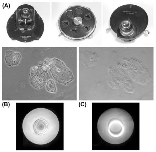
Figure 4. (A) Three different types of phase contrast condenser. The Leitz unit, on the left, has a flip-top top lens, and the centring screws for adjusting the phase annuli are held internally within the body. The Zeiss unit (middle) has its top removed to show the annuli for phase contrast [at 11 and 12 o’clock], three other apertures on the turntable have Wollaston prisms, and one position has a built-in aperture-diaphragm for transmitted-light bright field microscopy. The centring controls on this design can be seen around the rim at the bottom of the condenser turntable, the eccentric mechanism upon which they act is visible in the centre of the unit. The older CT&S unit on the right, has its centring controls clearly visible on the bottom at either side. This type of unit, although no longer made, is excellent for adapting to hold various filters, such as Rheinberg stops, because the annuli screw out of their holders very easily indeed.
(B) Appearance of epithelial squamous cells from the inside of the cheek when the phase contrast microscope is properly adjusted. The bright annulus in the front focal plane of the condenser is exactly coincident with, and superimposed upon, the darker phase plate built into the back focal plane of the objective.
(C) Lack of contrast, in the same image as 4B, arising from a mismatch of the annuli and phase plate, with a further corresponding photograph of the view of the back focal plane of the objective, as seen with a centring telescope.
The principle of the interference contrast microscope was described very briefly in my first paper [1]. In the DIC system, the necessary splitting of the light beam before, and recombining after, interaction with the specimen is achieved using Wollaston prisms. The construction and function of these prisms is explained lucidly in Bradbury & Evennett [15]. The design of DIC microscope developed by Nomarski is now the most commonly used because the Wollaston prisms are assembled so that they do not have to be placed exactly in the back focal plane of the objective, but may be situated at some distance away, which is easier to manufacture. Several designs of DIC microscope are possible, differing chiefly in the location of the second, beam combining, Wollaston prism. Modern designs usually have a separate prism for each objective, mounted in sliders inserted into slots, either in adapters fitted between the objective and nosepiece, or within the nosepiece itself. Alternatively, a single Wollaston prism fitted into the body tube of the microscope serves all the objectives. One prism (usually the second) is adjustable. This alters the optical path difference between the two coherent beams, and thus the contrast of the image. Correct alignment according to Köhler’s illumination principles is essential for successful DIC, and even a small misalignment will seriously reduce contrast, particularly if the height of the condenser is not adjusted correctly. These methods (phase contrast, Hofmann modulation contrast and DIC), which rely upon refractive index differences between the specimen and the mounting medium, were designed for use with colourless phase objects. However DIC has a considerable use in visualising unstained parts of otherwise stained or injected old preparations, as shown by Bracegirdle [16].
Reflected-light illumination
The simplest form of reflected-light, or epi-illumination, is from an external bulls-eye condenser mounted on a stand (Figure 5). This can be used to show surface relief. Unless it is used with very low powers, this form of illumination can be uneven. One way to provide even, multi-lateral, illumination for low powers is to use a Lieberkühn, the way reflected-light illumination was achieved before the development of vertical illuminators. For further details, see the following links [web addresses 9 & 10].
Reflected-light illumination employing any objective higher than 10 times will require a dedicated vertical illuminator. The simplest type uses a slip of glass set at 45°, and which can be adjusted to direct the light onto the optical axis. This so-called ‘coverglass illuminator’ is not very efficient because of the low reflectivity of the glass surface. This may not matter with polished surfaces of metals, which are highly reflective, but rocks and minerals generally possess much less reflectivity than metals, so the prism epi-illuminator, which gives much brighter illumination, is useful here. The prism, however tends to obscure much of the aperture of the objective, and both types of illuminator cause slight rotation of the non-axial rays of light, causing uneven illumination across the field of view. The Smith illuminator was developed to give sufficient illumination, yet reduce the rotations due to skew incidence, and so give a more evenly-illuminated field of view.
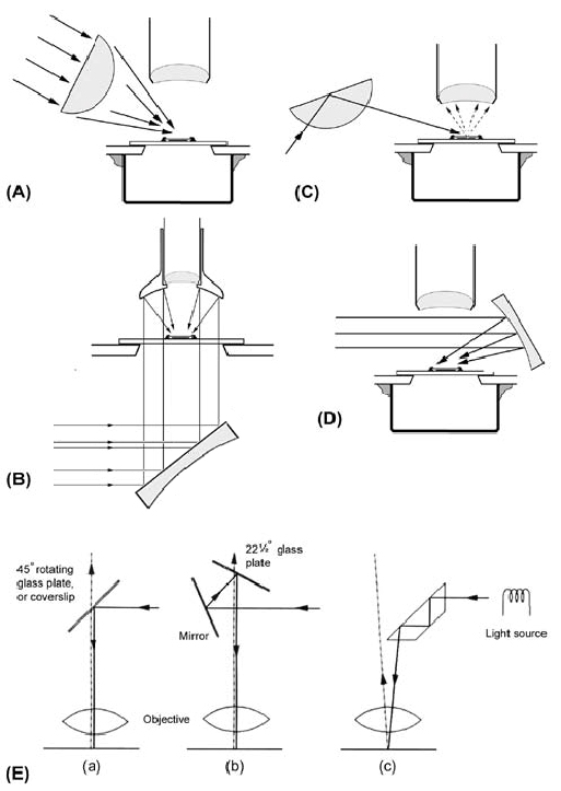
Figure 5. This figure shows various methods of using reflected light or epi-illumination (properly it is not referred to as incident illumination, since transmitted light can also be incident on the specimen from beneath). The dark wells in (5A), (5C), and (5D) are made from a cut-down 35 mm film canister and secured to the underside of the stage with ‘Blu-tack’.
(A) Using a bulls-eye condenser to direct unilateral illumination onto the surface of the specimen.
(B) Diagram of a Lieberkühn. This unit directs multilateral, annular, illumination onto the specimen from below.
(C) Using a bulls-eye condenser at a grazing angle to secure reflected-light dark ground illumination. The position of the flat surface of the condenser is such that the illumination is totally internally reflected onto the top surface of the specimen without directly entering the objective. The critical angle for glass is around 42°.
(D) Using a mirror to reflect light directed from a lamp. A mirror with a focus of about 50 mm is suitable.
(E) Diagram showing the three designs of vertical illuminator referred to in the text. (a) is the coverslip illuminator, (b) the prism illuminator, and (c) the Smith illuminator. This diagram has been adapted from Figure 1 in: Peckett, A. (1989) The Identification of Opaque Ore Minerals with the Reflected Light Microscope. Microscopy 36: 341-361.
Concluding remarks
In this paper it has not been possible to cover every aspect of contrast enhancement, for example dispersion staining [17], or reflection contrast microscopy [18; web address 11]. I have also deliberately omitted any practical reference to fluorescence microscopy, photomicrography, digital microscopy, or other means of controlling contrast by manipulation of the recording medium. This is for two reasons. First, few members of the Club will have the equipment necessary for preparing or examining specimens by fluorescence microscopy; and practical photomicrography has been ably dealt with elsewhere, with references cited in my first paper. Second, digital microscopy and photomicrography are separate subjects in their own right, and this paper is concerned only with contrast generation in the image within the microscope. For a good introduction to fluorescence microscopy, see Herman [20; web address 12]. For further, earlier, references on contrast-enhancement see Sanderson [19, 21] or the general Internet links given below.
Acknowledgements
It is a pleasure to thank friends who have helped me with the preparation of this manuscript. I am grateful to Peter Evennett for reading the draft and offering several useful suggestions from his undisputed wealth of teaching experience. I am also indebted to Barry Ellam and Klaus Kemp for allowing me to draw upon their considerable practical experience in microscopy and specimen preparation. This manuscript was finished shortly after the loss of my friend, Savile Bradbury; I wish to record the helpful discussions that I had with him, and encouragement that he gave me in writing this, as in all my work.
References
[1] Sanderson, J. B. (2000) The Theory of Contrast Control in the Microscope, Quekett Journal of Microscopy, 38:617-627.
[2] Evennett, P. J. (1993) Köhler Illumination: A simple interpretation, Proceedings of the Royal Microscopical Society, 28:189-192.
[3] Evennett, P. J. (1996) Technical Hints, Tips and Queries, Proceedings of the Royal Microscopical Society, 31:64-66.
[4] Barron, A. L. E. (1965) Using the Microscope, 3rd Edn. Chapman & Hall.
[5] Bradbury, S. & Bracegirdle, B. (1998) Introduction to Light Microscopy, 2nd. Edn. Microscopy Handbook 42, Bios Scientific Publishers, Oxford.
[6] Dodge, A. V. & White G. W. (1980) Further Observations on Glare in Transmitted Light Microscopy, Microscopy, 34:25-46.
[7] Sanderson, J. B. (1994) Biological Microtechnique, Microscopy Handbook 28, Bios Scientific Publishers, Oxford.
[8] Haynes, R. (1984) Optical Microscopy of Materials, International Textbook Company, Blackie, Glasgow.
[9] Adams, A. E.; MacKenzie, W. S. & Guildford, C. (1984) Preparation of a Stained Acetate Peel of a Limestone, Appendix 3, page 100 in Atlas of Sedimentary Rocks Under the Microscope, Longman, London.
[10] Baker, J. R. (1948) A New Method for Oblique Microscopical Illumination, Quarterly Journal of Microscopical Science, 89: 233-238
[11] Strange, A. (1989) New Developments in Variable Asymmetric Contrast, The Microscope, 37:355-376.
[12] Walker, M. I. (2000) Vitamin C by “Spikeberg” illumination, Quekett Journal of Microscopy, 38:601
[13] Strange, A. (1989) Rheinberg Stop Contrast Illumination, Microscopy 36:337-340
[14] Trett, M. (1980) Techniques for Controlled Dark-ground and Oblique Illumination for use with the Light Microscope. Proceedings of the Royal Microscopical Society, 17:309-310.
[15] Bradbury, S. & Evennett, P. J. (1996) Contrast Techniques in Light Microscopy, RMS Handbook 34, Bios Scientific Publishers, Oxford.
[16] Bracegirdle, B. (1993) A new look at old slides. Microscopy & Analysis 34:33-35.
[17] Laughlin, G. J. (1992) Microscopy in the Identification of Asbestos, Proceedings of the Royal Microscopical Society, 27:9-15.
[18] Ploem, J. S. et al. (1995) Reflection-contrast Microscopy: An Overview, Proceedings of the Royal Microscopical Society, 30:185-92.
[19] Sanderson, J. B. (1994) Contrast in Light Microscopy: An overview. Proceedings of the Royal Microscopical Society, 29:263-270.
[20] Herman, B. (1998) Fluorescence Microscopy, 2nd. Edn. RMS Handbook 40, Bios Scientific Publishers, Oxford.
[21] Sanderson, J. B. (1998) Contrast Enhancement Techniques for Light Microscopy, in Cell Biology: A Laboratory Handbook, 2nd Edn. Vol. 3:15-33, Academic Press, San Diego, CA.
An additional reference specifically dealing with contrast enhancement in reflected-light microscopes, brought to my attention after the publication of this paper, is:
Hammond, C. (2001) Exploiting Light Microscopy Contrast Techniques to the Full, pages 69–87. In: Quantitative Microscopy of High Temperature Materials, Eds. A. Strang & J. Crawley. Institute of Materials. Book No. 0732, ISBN 1-86125-109-2.
Web addresses (URLs) referred to in the text
1. Buehler Ltd (2001) Buehler’s Technical Information Guide: Grit Equivalency Guide & Etchants
2. Scinfitech (2001) Etchants for microscopic examination of carbon and alloy steels
3. Abineri, K. W. (1999) The Examination of Microfossils, Nannofossils and other Microscopical Objects Using Cellulose Lacquer Rock Peels
4. http://www.uni-wuerzburg.de/mineralogie/palbot/tools/preparation.html
5. Walker, D. Oblique Illumination – or why knocking the mirror or condenser out of alignment sometimes helps!
6. James, P. (2000) Illumination Variants (Part 1). A report on an interesting variant of oblique illumination
7. Bradbury, S. Rheinberg Illumination
8. Thomson, D. The Magic of Polarised Light
9. Ells, W. (1998) Incident Lighting and the Lieberkühn Speculum
10. Walker, D. (1998) Simple ‘top lighting’ with a compound microscope … or how to study subjects you can’t get light through!
11. http://members.tripodnet.nl/fprins/
12. Bechtol, K. B., Hanzel, D. K. & Bee Choo Liang Amersham Biosciences Technical Note # 57 Understanding Fluorescence
Other useful Web addresses – on light microscopy and contrast enhancement
http://www.northwestern.edu/bme/coursepages/Lecture81.pdf
http://www.northwestern.edu/bme/coursepages/Lecture91.pdf
Davidson, M. W. & The Florida State University (2009) Introduction to Optical Microscopy, Digital Imaging, and Photomicrography
Address for coloured filter material
Lee Filters, Central Way, Walworth Industrial Estate, Andover, Hampshire, SP10 5AN, United Kingdom
Tel: +44 (0)1264 366245