

4. Objectives I
The objective I – types, aberrations
There are three individual pieces of glassware used to illuminate the specimen and form the image. These are the condenser, objective and eyepiece(s), and each will be dealt with separately in this and the next two articles in the series. We will then return to the objective in part 7, for it is of prime importance in forming the image, and is usually the best engineered (and hence most expensive!) individual piece of equipment on the microscope. Essentially, the objective is the microscope. Since a large part of the value of your microscope is represented by the objectives rather than any other single item of equipment, it is worth knowing the about the different types of objective that are available.
The magnification ratio of a microscope objective is very large, ranging from ×1 right up to ×100. The optical corrections must therefore be good, so that the image quality is degraded as little as possible. The manner in which an image is formed was dealt with in part 2 of this series. In an ideal world any lens would reproduce a perfect image of the object but, due to the nature of light itself, it is not possible to do this. Image formation is not only due to the diffraction of light, but diffraction also limits formation of the perfect image. Those who wish to read more are referred to C. A. Taylor’s book Images in the Wykeham Science Series. The imperfections in the image that interest us are called aberrations. There is no getting away from aberrations whatever the imaging system, be it a microscope, a camera, or even the electron microscope.
There are seven principal types of aberration, namely:
- spherical aberration
- [longitudinal] chromatic aberration
- field curvature
- chromatic difference of magnification or lateral chromatic aberration
- astigmatism
- coma
- distortion
Of these seven aberrations, the effects of spherical and chromatic aberration may be seen across the entire field of view, whereas the remaining aberrations get progressively worse in those parts of the image formed further and further from the optical axis. All the aberrations, apart from the two chromatic forms, are present with monochromatic light of a single wavelength.
Astigmatism, coma and distortion are all characterised by different zones of the objective magnifying the image to different extents. In modern objectives these three aberrations are routinely minimised by the manufacturer, and so need not concern us. For an explanation of these aberrations and the others, see the recently-published excellent work by Bradbury & Bracegirdle (1998). The reader who wishes to test older objectives for these aberrations is referred to Fletcher (1988). Field curvature, too, can be well-corrected and may be controlled by the microscopist according to which objectives he or she wishes to buy.
Chromatic aberration
The refractive index of glass is not constant throughout the entire spectrum. This phenomenon is called dispersion. Thus if a lens is made from a single type of glass, white light from an object point will not be brought to a common focus, but the focal points for each wavelength (say, red, green and blue) will be spread along the optical axis. Hence at any one focal point, say green, a purple halo will be seen surrounding the object due to the combination of the out-of-focus blue and red rays. This is illustrated in Figure 13 of White (1966) on page 29. Chromatic aberration can, obviously, be eliminated by introducing monochromatic illumination using filters. Since crown glass and flint glass possess different dispersive powers, it is possible to combine lens elements of these two materials so that longitudinal chromatic aberration is minimised for selected wavelengths.
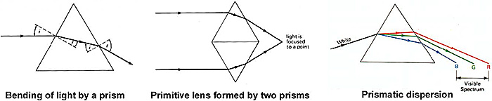
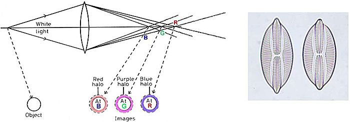
Figure 1. Illustration taken from: from White G. W. (1966) Introduction to Microscopy, Fig. 13, page 29. Butterworths.
Lateral chromatic aberration occurs in the objective because the magnified size of an image will vary according to the wavelength of the illuminating light. Thus, particularly at the edges of the field of an uncorrected system, a blue image will be seen towards the axis surrounding the main image and a red one away from the axis.
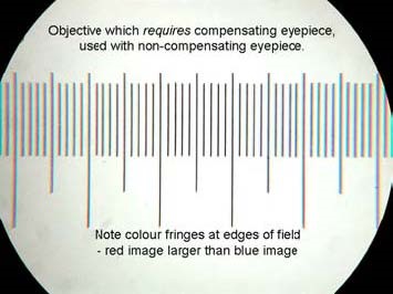
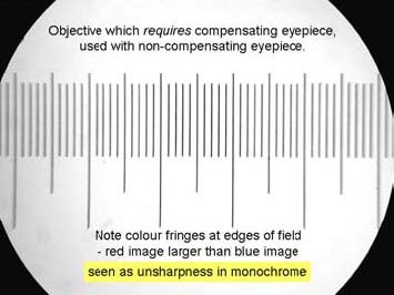
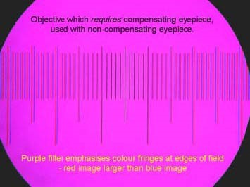
Figure 2. Taken from: Powerpoint demonstration courtesy of Peter Evennett, Royal Microscopical Society Light Microscopy teaching course.
Fortunately, it is possible to design a reverse ‘error’ into the eyepiece to eliminate this chromatic difference of magnification from the final image. Such an eyepiece is called a compensating eyepiece. This is why high quality objectives have to be matched with their intended eyepieces, and why objectives and eyepieces from different manufacturers should generally not be mixed. Another reason for not mixing objectives is because each manufacturers objectives are designed to be ‘parfocal’ and ‘parcentral’ so that only minimal focusing and adjustment of the illuminated field is necessary once a different objective is swung into place.
Spherical aberration
Where the shape of the lens surface (the ‘figure’ of the lens) approximates a sphere, the light rays emanating from the optical axis near the object will come to a focus at a different point from those rays formed near the periphery of the lens. The zone of confusion [see Figure 1.12 and 1.13 in Bradbury & Bracegirdle (1998)], leads to the image suffering from spherical aberration; it is blurred and often lacking in contrast.
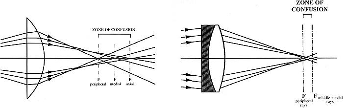
Spherical aberration in a simple lens (left). Due to the curvature of the lens, the axial rays are focused at a point further from the lens than the medial (peripheral) rays. No sharp image exists, and there is an extensive ‘zone of confusion’. This aberration is corrected by combining a positive and negative lens, reducing the spherical aberration considerably. The middle and axial rays now come to a focus at a common point, reducing the zone of confusion.
Figure 3. Illustration taken from: Bradbury S. & Bracegirdle B. (1998) Introduction to Light Microscopy, Figures 1.12 & 1.13, pages 13–14. Bios Scientific Publishers, Oxford.
Since most aberrations get worse the further off the optical axis the image point lies, then the higher the aperture (and hence resolving power) the more difficult it is to correct the defects. This is why the best quality objectives of the highest numerical apertures are usually the most expensive. Because spherical aberration affects dry objectives more than a similar immersion objective of equivalent numerical aperture, the former so-called ‘high-dry’ objectives are fitted with correction collars to aid in minimising the effects of image blurring due to spherical aberration. Just how chromatic and spherical aberration may be controlled and corrected on both monocular and binocular microscopes will be dealt with in the second article on objectives in part 7.
Up until the beginning of the nineteenth century, the component optical parts of the microscope were made in an empirical fashion. It was not until 1830 that J. J. Lister devised a rational method of combining a plano-concave element of flint glass cemented to a plano-convex element of crown glass. By this means both spherical and chromatic aberration were corrected for the two focal points of the lens. For top quality imaging, it is also possible to buy ‘aplanatic-achromatic’ condensers which are corrected for spherical and chromatic aberrations.
It is expensive to make and grind high-quality lenses, therefore objectives are offered with differing degrees of correction to suit everyone’s purpose. Today’s basic achromat objective without flat-field correction is still a much better corrected lens that even those of the highest quality produced before the introduction of Lister’s achromatic doublet. Those readers who wish to read further about the historical evolution of image quality in the microscope objective are referred to Bradbury (1967) and Bracegirdle (1978).
Field curvature
Up until the Second World War, most objectives lacked any form of flat-field correction. Nowadays the need for flat-field objective lenses corrected for field curvature is the norm because of the demands of photomicrography and the increased use of the microscope as an analytical tool. Therefore, ‘plan’ objectives (planachromats, plan-apochromats etc.) are sold. ‘Plan semi-apochromat’ is a bit of a mouthful, so ‘plan-Neofluar’, ‘plan-Fluorite’ and similar derivations, are brand names used for this type of corrected objective.
To summarise: coma, distortion and astigmatism are minimised during manufacture. Field curvature is either accepted, or a series of ‘Plano’ objectives with flat fields is purchased. Chromatic difference of magnification is corrected by using the objective in conjunction with the proper eyepieces. Longitudinal chromatic aberration is corrected either by using a green filter and the image recorded using black-&-white film, or else the best apochromats are used to minimise the ‘secondary spectrum’ of residual colour in the image. Spherical aberration is minimised by using objectives at the right tube length with the right thickness of coverslip and mounting media (if any) for the preparation.
You may ask, therefore, “what is the best choice I can make of a series of objectives?” Beginners usually think that the highest magnification objectives are best. This, however, is a mistake. A lower power objective will have a greater field of view and can be used to survey the object. In any case, high powers have to be either oil or water-immersion, because the numerical aperture usually increases proportionally with magnifying power. There is an advantage in having a battery solely comprising dry objectives for ease of use, but the NA of the highest power will be limited to 0.95, and for equivalent numerical apertures an immersion objective will give a crisper, brighter image than a dry lens.
Where there is a lot of rapid work requiring an immersion objective, consider using water immersion, as it is easier to clean than an oil-immersion objective. My own choice is to have a ×2.5, a ×10, and a ×25 dry objective with a ‘high-dry’ ×40 objective with a correction collar (although it can be ‘fiddly’ adjusting the correction collar) and a ×63 oil-immersion objective. If I require better quality at ×40, I will use a multi-immersion objective which gives freedom to choose water or oil as the immersion fluid, and further allows me to eliminate the spherical aberration most precisely.
In the mid-nineteenth century the Royal Microscopical Society laid down standard dimensions so that, as far as possible microscope objectives could be interchanged between stands. Although there has been a recent trend for designers to drop these old standards and use their own-brand parameters, one consensus that has remained is the use of coloured rings on modern objectives to distinguish the magnifying power at a glance. The series follows the colours of the spectrum:
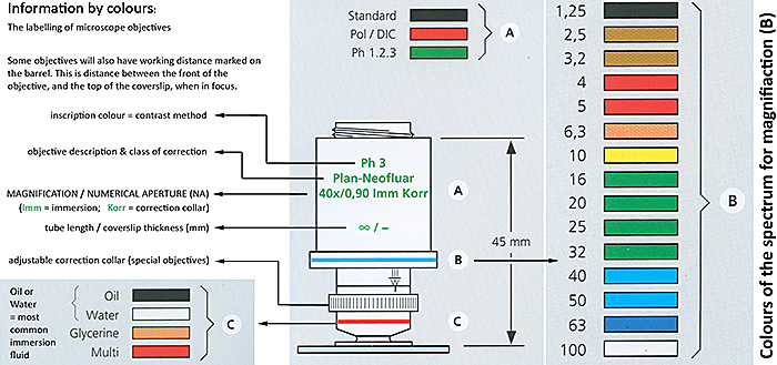
Figure 4. Adapted from: Microscopy from the very beginning, Carl Zeiss. Used with permission.
Magnification = Colour code of ring
Phase contrast: Green lettering; Pol, DIC: red lettering
See also: Molecular Expressions Microscopy Primer: Anatomy of the Microscope – Objectives: Specifications and Identification
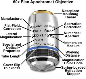 Figure of an objective, added to the PDF file, and taken from: http://micro.magnet.fsu.edu/primer/anatomy/specifications.html
In addition there are extra bands to indicate which immersion fluid to use. A black band indicates that oil is required; a white band stands for water. Oil is the most commonly-used immersion fluid, followed by water. Brown/orange is used for glycerine, and a red band for a multi-immersion objective. This latter type is quite rare, but the lens elements are arranged so that they can be altered in exactly the ‘high-dry’ objective, mentioned above, to compensate for spherical aberration residual in the image.
I started by stating that there are three individual pieces of glassware used to illuminate the specimen and form the image. The eyepiece is needed to present the magnified primary image, formed by the objective, to the eye. Because the primary image plane, formed in the eyepiece, is conjugate with the specimen plane, the eyepiece is the place where you can superimpose measuring scales to quantify the image. In the next part in the series, I will look at the different types of eyepiece, and how to perform simple measurements.
References
Bracegirdle, B. (1978). The performance of seventeenth and eighteenth century microscopes. Medical History 22/2, 187–195
Bradbury, S. (1967). The quality of the image produced by the compound microscope: 1700–1840. Proceedings Royal Microscopical Society 2/1, 151–173
Bradbury, S. & Bracegirdle, B. (1998). Introduction to Light Microscopy, Bios Scientific Publishers, Oxford.
Fletcher, J. R. (1988). The star test for microscope optics. Microscopy 36/2, 154–9.
Taylor, C. A. (1978). Images Wykeham Publications, London. ISBN 0-85109-620-4
White, G. W. (1966). Introduction to Microscopy, Butterworths, London.
Carl Zeiss, Microscopy from the very beginning
© Jeremy Sanderson, Oxford, 2010