

2. Elementary optics
Elementary optical principles – image formation
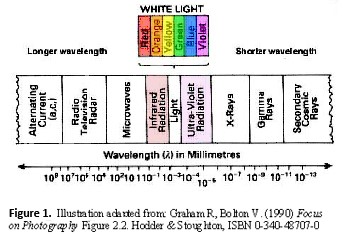
This second article considers the fundamental principles that govern firstly how an image is formed from rays of light, and secondly how the eye (the ultimate receptor in any optical instrument) influences the function and design of the microscope. Optics is defined as the study of the laws of light, the medium used by our microscopes. Visible light is that part of the electromagnetic spectrum with a wavelength from about 400 nanometres (nm) to 700 nm. A nanometre is one millionth part (1×10⁻⁶) of a millimetre, and one-thousandth part (1×10⁻³) of a micrometre (µm). Below 400 nm we have ultraviolet radiation and X-rays, and above 700 nm infrared and microwaves, TV, radio and audio frequencies.
The action of light can be understood by assuming that the light travels in straight lines, except when refracted (or bent) by lenses. This is the field of geometric optics
An alternative approach is to consider light in the form of waves (wave optics). This latter approach is used to explain the phenomena of diffraction, and of image formation due to interference of coherent waves of light.
The wave nature of light also enables us to derive the limit of resolving power of the light microscope.
For an elementary understanding of the action of the light microscope we need not be concerned with wave optics. Instead we can use simple elements of geometric optics to characterise the action of the lenses.
When light passes from air (a less dense medium) into glass (a denser medium), it slows down, and if it enters the glass at an angle, it is bent (refracted) towards the plane normal to the surface of the glass. The ratio of the velocities of light passing through a medium and through air is called the refractive index of that medium. A ray normal to the surface of a medium, however, will pass through the medium without deviation. When the ray leaves the glass medium (RI = 1.5) and travels into the less dense air (RI = 1.0), it is bent away from the normal.
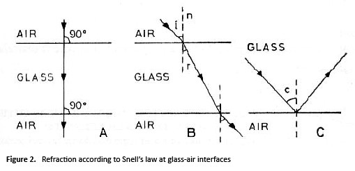
(A) Light at right angles (normal) to a plane parallel plate of glass is transmitted without deviation. (B) A ray inclined to the normal undergoes two deviations, emerging parallel to its original direction, but displaced laterally. (C) A ray in glass incident at more than the critical angle, c, is totally reflected. The sine of the critical angle is the reciprocal of the refractive index. n = normal at point of incidence, i = angle of incidence, r = angle of refraction.
Refractive Index (RI) = sin i/sin r. sin c = 1/RI
The action of a lens depends upon the phenomena of refraction, for a lens may be thought of as a series of minute prisms, and each surface, or figure, of the lens as an infinite series of glass-air interfaces.
For a good illustration of this, see Abbott (1986, p. 262). The word focus derives from the Latin for fireplace, which reminds us of the early uses of lenses as burning glasses (infra-red radiation is focused too!)
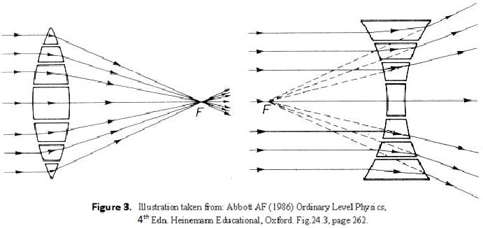
Both convex or positive, and concave or negative, lenses are used by microscope designers, often grouped together as a series of doublets to form a single optical unit. However, in order to understand their action, we can think of the microscope condenser, objective and eyepiece lenses as single, thin convex lenses. Each lens has two focal points, front and rear, and the distance from the centre of the lens to the focal point is the focal length (usually designated by the letter f) of that lens. The plane passing through the focal point normal to the axis is the focal plane of the lens. Three properties enable us to construct a ray diagram for a particular lens:
- When parallel rays of light (i.e. from infinity) enter a lens, they come to a focus at the rear focal point of that lens.
- Conversely, rays passing from the object, through a focal point will be refracted by the lens and leave it parallel to the optical axis.
- Rays that pass through the centre of the lens pass through undeviated.
Ray diagrams help us to understand the action of lenses. By convention rays are considered to travel from left to right. Distances in front of the lens are considered negative (designated ‘u’), and those behind the lens as positive (‘v’). A positive lens thus has a positive focal length, and a negative lens a negative focal length. A real image is one which can be focused onto a screen (Figure 4), whereas a virtual image (e.g. that at A′ in Figure 5, or IB in Figure 7), though it can be seen by the eye, cannot be focused onto a screen. When the object is placed at the first focal point, a real, inverted, image is ‘formed’ at infinity – parallel light leaves the lens and the eye sees only a blurred patch of light. Conversely, the image of an object ‘at infinity’ is formed at the second focal point of the lens. These phenomena are exploited in the design of Köhler illumination.
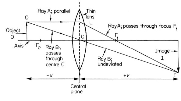
Figure 4. Formation of an image by a convex lens. The object is placed beyond the focal point, F2, and the image is real and inverted
Magnification = +v/−u
(Plus (+) indicates the image is upright, Minus (−) indicates the image is inverted)
When an object is placed at twice the focal length (2f), a real, inverted image is formed, the same size as the object. An object is placed between one and two focal lengths from the lens, forms a real, inverted, magnified image between 2f and infinity.
This is how the objective functions; as the distance v increases so does the magnification, since magnification is given by v/u. Conversely, an object placed beyond 2f will form a real, inverted, image reduced in size between one and two focal lengths from the lens.
An object placed within the focal length of the lens forms an erect, magnified, virtual image. This is how both the eyepiece and a magnifying glass or one-stage (simple) microscope function. Illustrations of all these different actions of lenses may be found in any good physics text book. I recommend that by Abbott (1986, pp. 262–264).
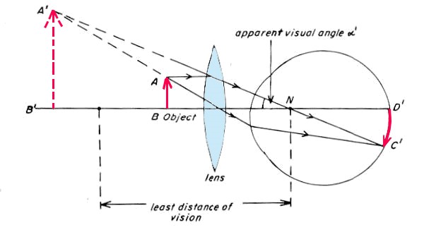
Figure 5. A simple lens producing a virtual image at A′ of an object A–B at or within the focus of the lens.
Illustration taken from: Bradbury, S. (1967) The Evolution of the Microscope, Fig. 1.2, p. 11. Pergamon.
The compound light microscope is equivalent to three lenses: an objective, eyepiece and condenser. A fourth lens is used to achieve Köhler illumination. In any microscope three fundamental parameters govern the successful use of the instrument. These are resolving power, contrast (or visibility) of the specimen, and magnification, in that order of importance.
The most important function of the microscope is to resolve fine detail, which must be rendered sufficiently visible and presented at a suitable enlargement to the eye. Dickens’ Sam Weller (The Pickwick Papers) remarked:
“Yes I have a pair of eyes … and that’s just it. If they was a pair o’ patent double million magnifyin’ gas microscopes of hextra power, p’raps I might be able to see through a flight o’ stairs and a deal door…”
To the layman microscopes are about magnification, but the magnifying power of the microscope merely serves to present the resolved detail at the ideal size to the eye.
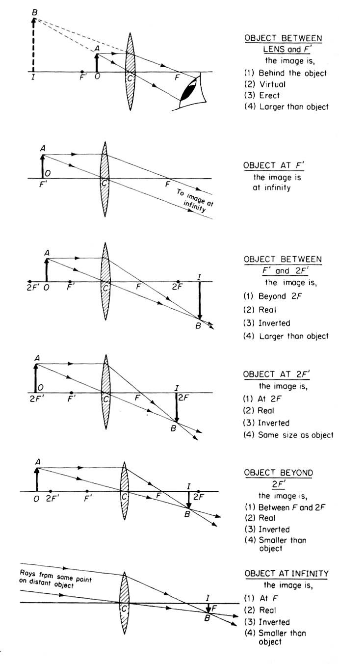
Figure 6. Illustration taken from: Abbott A. F. (1986) Ordinary Level Physics, 4th Edn. Heinemann Educational, Oxford. Figs. 24.4 – 24.9, p. 264.
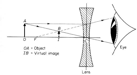
Figure 7. Illustration taken from: Abbott A. F. (1986) Ordinary Level Physics, 4th Edn. Heinemann Educational, Oxford. Fig. 24.10, p. 265.
Let us now consider the eye. The retina is a light-sensitive ‘re-useable-film’ comprised of discrete receptors (rods and cones) linked to the brain. In order for closely-apposed detail to be perceived as discrete, two distinct receptors must be stimulated and be separated by a third unstimulated rod or cone. If, on the other hand, adjacent receptors are stimulated, the fine detail remains unresolved. A young, healthy, eye can resolve 100 µm, but a more realistic value is 300 µm.
When the eye is completely relaxed, images at infinity are brought to a focus at the retina. When the object is at a distance from the eye, ( e.g. O′ – O′ in Figure 8) the visual angle (A) is small with a consequent small image on the retina. As the object is brought nearer the eye, the curvature (and hence the power) of the lens of the eye is increased to increase the visual angle subtended of the light to that denoted by B in Figure 8. The retinal image is consequently larger.
The eye can alter its focus, (accommodation) and an object may be seen clearly until it is about 250 mm (10 inches) away from the eye. This is the least distance of distinct vision, or near point (Figures 5 and 8). The power of accommodation is gradually lost (presbyopia) from between 30 to 60 years of age. This can be useful in focusing for photomicrography (this will be discussed in part 9).
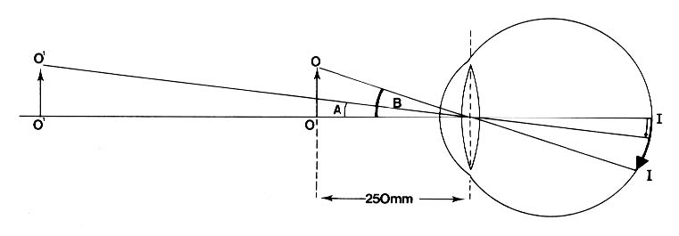
Figure 8. The increase in visual angle effected by bringing an object closer to the eye
Illustration taken from: Bradbury, S. (1967) The Evolution of the Microscope, Fig. 1.3, p. 11. Pergamon.
The action of a single convex thin lens, such as a magnifying glass or simple microscope, is shown in Figure 5. The eye perceives a magnified image of the object at the place where the angles of the rays of light from the virtual image are equivalent to those leaving the magnifying lens. The lens thus has the effect of increasing the visual angle, and increasing the size of the real image formed on the retina.
The smaller the focal length in relation to the least distance of distinct vision, the greater the magnifying power of the lens.
There is a limit to the magnifying power of a simple microscope, which is determined by the focal length, and also the closeness with which the lens can be held near the eye. For this reason the two-stage, or compound, microscope (Figure. 9) is used for convenience and because it can be arranged to give greater magnifying power.
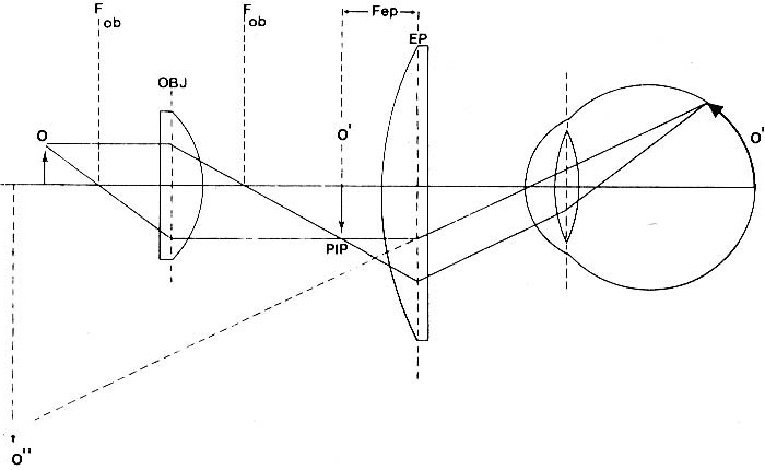
Figure 9. The arrangement of lenses in a compound microscope.
The object is at 0, the real inverted primary image produced by the objective (O′) is at PIP – the primary image plane – and the final virtual image formed by the eyepiece at 0″.
Illustration taken from: Bradbury, S. (1984) An introduction to the optical microscope, 1st Edn. Figure 8, p. 7. RMS Handbook No. 1, Oxford University Press.
References
Abbott, A. F. (1986). Ordinary Level Physics, 4th Edn. Heinemann Educational, Oxford. ISBN 0-435-67010-7
Barron, A. L. E. (1965) Using the microscope. 3rd rev. Edn. Chapman & Hall, London. ASIN B0006BML0K
Bradbury, S. (1984) An introduction to the optical microscope. Oxford University Press, Oxford. ISBN 0-19-856401-5
© Jeremy Sanderson, Oxford, 2010