

5. Eyepieces and measurement
The eyepiece – different types. Measurement in the microscope
The image formed by the objective is focused at the primary image plane. If we were to have the visual acuity of a bird of prey, there would be no need for an eyepiece, for all the detail resolved by a 100 times objective would be clearly visible. Likewise, if a CCD or analogue video camera is used to view the image, an eyepiece may not be required at all. In some cases where the image has to be compressed in order to fit onto a CCD faceplate, a reducing lens will be needed! Human visual acuity is limited by the structure of the retina (see part 2). We therefore require the eyepiece (also sometimes called an ocular) as a secondary magnifier to present the detail inherent in the image at the primary image plane to the retina.
The image of the specimen is subsequently imaged firstly in the primary image plane (PIP) and then secondly at the retina. These two images reside in the same set of conjugate planes, the imaging set (see part 3). The PIP is thus an ideal place at which to place a scale that will be superimposed on the image of the specimen, seen in the retina with the eye. The eyepiece is therefore important when scales must be used to measure the image. The mechanical position of the PIP within the eyepiece varies according to the type of eyepiece. Theoretically, only a single (field) lens is required as a secondary magnifier (see Figure 9, part 2), but it would in consequence have to be very large (Figure 1, left). A second (eye) lens is added to reduce the size of the PIP (Figure 1, right). Since the PIP is now moved closer to the objective [at A′–B′] instead of its former, dashed, position [A2–B2) in Figure 1 left, the field of view is increased.
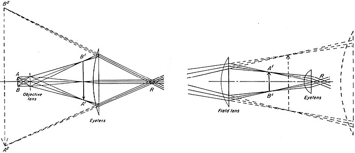
Figure 1. Function of the eye lens in the eyepiece
Image taken from: Bradbury, S. (1967) The Evolution of the Microscope, Figs. 1.4 & 1.5, pages 11, 14. Pergamon.
The rays of light leaving the eyepiece intersect at the exit pupil, or aperture, of the eyepiece, sometimes called by its older name of Ramsden disc. This eyepoint is the place where the eye is placed in order to see the whole field of view, and is indicated by the letter ‘R’ in Figure 1, above. Beginners in microscopy often find difficulty in holding their head sufficiently steady at the correct height at the plane of the exit pupil for the field(s) of view not to move uncontrollably. With higher magnification eyepieces, the exit pupil is formed closer to the top eye-lens of the eyepiece. This sometimes makes the entire field of view difficult to see, particularly for spectacle wearers, and so manufacturers often make ‘high-eyepoint’ eyepieces, and include rubber cups around the eyepiece to assist the observer in holding their head at the correct height. These rubber cups can be folded down out of the way if desired. As with objectives, the higher the magnification of the eyepiece, the smaller is the field of view.
Types of eyepiece
There are several types of eyepiece, since these must be corrected for optical errors in the same way that objectives are corrected (see part 4). The Huygenian eyepiece or negative eyepiece, (now called the internal diaphragm eyepiece) has the PIP located between the eye-lens and field-lens, Figure 2(a). The Huygenian eyepiece is the simplest type of eyepiece, and works well with achromatic objectives, but it will cause distortion of image points off the optical axis.
To correct for this distortion in micrometry, the Ramsden (external diaphragm or positive) eyepiece was developed, Figure 2(b). Any measuring scale inserted at the PIP is also more easily accessed and fitted. The Ramsden eyepiece eliminates distortion from the image of any scale in the eyepiece, but is not fully achromatised. This is corrected for in the Kellner (or achromatised Ramsden) eyepiece, which has the single eye-lens replaced by doublets, Figure 2(d).
In some cases the eyepiece of the microscope is also used to correct the chromatic difference of magnification found in semi-apochromat and apochromat objectives. Chromatic difference of magnification was covered in part 4 of this series on the objective.
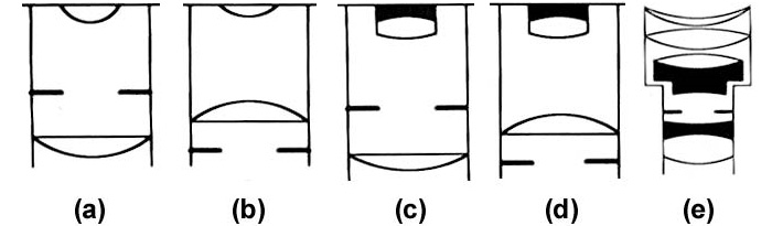
Figure 2. Types of eyepieces. 2(a) Huygenian; 2(b) Ramsden; 2(c) achromatised Huygenian eyepiece; 2(d) achromatised Ramsden (Kellner); 2(e) modern ‘Periplan’ eyepiece, designed to reduce the curvature of field often associated with simple Kellner eyepiece.
Illustration taken from: Bradbury S. & Bracegirdle B. (1998) Introduction to Light Microscopy, Fig. 5.16, page 79. Bios Scientific Publishers, Oxford. ISBN 1-859961-21-5
The problem of correcting the residual chromatic difference of magnification, or lateral chromatic aberration, in the primary image of apochromatic, semi-apochromatic and high-magnification achromat objectives was solved by the use of specially computed eyepieces. Such eyepieces are known as compensating eyepieces, and are designated with a K, C, or the word COMP in the nomenclature engraved on the top face of the eyepiece.
It is important that these compensating eyepieces are used with the objectives that the manufacturer intended: any mis-matching will only compound the optical errors that have been designed so as to cancel out. Failure to use the correct eyepiece with an objective designed for use at a finite tube length (e.g. 160 mm) results in contrasty objects at the periphery of the field of view appearing with a red fringe on their outer diameters and a blue/violet fringe on the inner sides. With the use of infinity-corrected objectives, the tube lens is used to correct this residual chromatic error of the objective.
Eyepieces intended for measurement (often called ‘micrometer’ eyepieces) or those for specific counting or sampling carry a graticule etched onto a circular glass disc in the plane of the field-limiting plane of the eyepiece. In such eyepieces the eye lens has some form of focusing mechanism, to allow the graticule to be imaged clearly. For greater accuracy, a filar micrometer eyepiece is used, and its function is explained below.
The pointer eyepiece, as its name suggests, has a moveable pointer mounted in the primary image plane. In some cases the pointer also moves axially, in order that the entire field of view can be covered. For polarising microscopy, goniometer eyepieces, having a 360° protractor scale, can be obtained which allow the interfacial angles of crystals to be measured.
For assessing volume fractions and counting areas in statistical work, a net graticule is used in the PIP. A net graticule comprises a series of squares (rather like a chessboard of transparent squares) covering the field of view. Drawing eyepieces are arranged to include a drawing prism mounted above the eye-lens so that the image may be transferred onto a sheet of paper and recorded. Drawing can also be simplified by using a net graticule: the image is copied directly onto squared paper using the net as a guide (see part 9 – Image Recording). Negative projection eyepieces, employing a concave lens, are used to transfer an enlarged real image onto film for photomicrography. A further advantage of using these negative lenses is that a very flat field can be obtained, as the concave lens cancels out the field curvature produced by the objective.
Practical use of the eyepiece
Since people have differing strength eyes (measured in dioptres), which also often differ between eyes of the same person, a means of focusing the eyepiece is built into the binocular heads of better quality microscopes. The dioptre controls of the eyepieces should be set to provide fatigue-free observation. For a microscope with one dioptre control on the binocular head, set the microscope using the non-adjustable eyepiece, then adjust the focusing on the other eyepiece so that both fields of view are sharp and both eyes relaxed. Where there are two dioptre controls, set up the microscope initially using your dominant eye and adjust the focus for the other eye afterwards. In both cases try to keep the unused eye open, neither screw the eyes up, but rather relax them – you should be aiming to ‘look through’ the microscope to infinity: closing the unused eye will pull on the lateral muscles and alter the focus of its partner. Fatigued eyes result if the eyepieces are not correctly adjusted for relaxed viewing of an image at infinity – which is how the microscope is designed to be used.
To ensure that the microscope will remain in focus throughout its entire magnification range, proceed as follows. Set the microscope up using the finest detail on the specimen, and change to the highest magnification dry objective. Check that the interocular distance has been set for comfortable viewing. Focus precisely using the fine focus control. If one of the eyepieces has a photographic frame or graticule, these should be set before proceeding to the next step. Change to the lowest magnification objective. Do not readjust the microscope focus control, but focus the image for each eye by using the individual adjustment for each eyepiece. For further details, see Evennett (1996).
Linear measurement in the microscope
The easiest means of measuring a distance is to use the graduated horizontal and vertical scales on the mechanical stage. This is not a very accurate means of measurement, but the accuracy may be improved if the stage is fitted with a vernier scale.
In all types of eyepiece a fixed platform is often found at the plane of the PIP so that a scale (usually called a graticule) can be inserted into the eyepiece, and superimposed on the image of the specimen seen at the PIP. The Ramsden, or external diaphragm eyepiece presents the most conveniently-placed location for the scale.
When the graticule, which is marked out in arbitrary units, is calibrated properly, the size of the specimen can be calculated. A scale-bar can then be added, for example, in any published image.
A typical graticule is shown in Figure 3(a). The ruled scale is formed either by deposition of a thin metal film onto the glass substrate, or photographically; the former is more accurate (see Figure 3.2, Bradbury, 1991). This scale is usually divided into 10 or 100 divisions for ease of calculation [Figure 3(b)]. These are uncalibrated arbitrary divisions, whose absolute linear measurement in the PIP depends upon the magnification of the objective and any intermediate optical elements (eg an ‘Optovar’ magnifier). The scalebar [Figure 3(c)] is ruled in the same way as a graticule, but onto a coverslip which is mounted onto a microscope slide. The scalebar consists of a known ruled unit (usually one millimeter divided into 100 ten micrometer (µm) divisions [3(d)], with fiducial lines every 50 and 100 µm) and is paced onto the stage in place of the specimen. Since the image of the scalebar is superimposed [Figure 3(e)] onto that of the graticule located at the PIP, the latter can be calibrated in known units. Fewer divisions are shown on the graticule in Figure 3, for clarification.
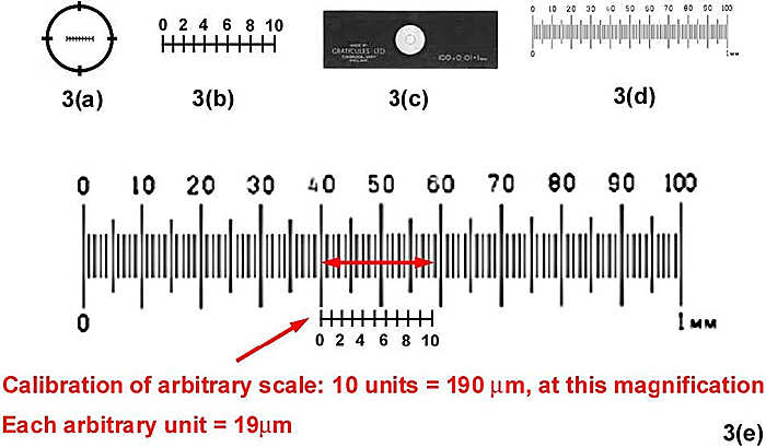
Figure 3. Measurement using a graticule fitted into a ‘micrometer’ eyepiece.
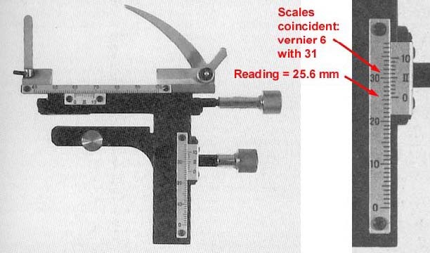
Accurately-made graticules and scalebars may be purchased from various suppliers, but one of the best known is the firm of Graticules Ltd of Tonbridge, Kent. Those wishing to learn more about measurement and the use of the microscope as an elemental tool are referred to Bradbury’s comprehensive treatise Basic Measurement Techniques for Light Microscopy. A more accurate method of taking linear measurements is by using a filar micrometer eyepiece. In this case the graticule is arranged so that turning a graduated drum on the side of the eyepiece moves a fiducial line either side of a central, static, zero line. The drum is marked in arbitrary units, and these are calibrated in the same way as a micrometer eyepiece. Finally, a more accurate method still is use an image-shearing eyepiece, but a full description of this equipment is outside the scope of this article. The image-shearing eyepiece is only suitable for use with a monocular stand. Those interested in a protocol for the use of both these pieces of equipment are referred to Bradbury (1991).
References
Bradbury, S. (1991) Basic Measurement Techniques for Light Microscopy. Royal Microscopical Society Handbook No. 23. Oxford University Press. ISBN 0198564260
Evennett, P. J. (1996) Queries, Proceedings Royal Microscopical Society March 1996 Vol. 31/1: 64-6601985642600198564260
Graticules Ltd, now Pyser-SGI
© Jeremy Sanderson, Oxford, 2010