

Sartory Instruments Ltd – A Very British Enterprise
 By Carel Sartory
Introduction
The years just after the 1939–1945 World War witnessed a period of reconstruction in Great Britain, especially in manufacturing and technical engineering.
During the war these businesses were almost entirely engaged in armament and military equipment manufacturing under the control of the Ministry of Supply. After the war the focus shifted to more constructive requirements and a programme of rebuilding and re-equipping of schools, technical colleges and universities was seen as a major requirement by the post-war government.
It was to capitalise on this demand that P. K. (Peter) Sartory and L. J. (John) Bunford formed the firm of Sartory Instruments Ltd in 1949.
Peter Karel Sartory (1908–1982), who was the driving force behind the new company, was a largely self taught optical and mechanical engineer, who had from childhood been fascinated by microscopes and telescopes. He joined both the Royal Microscopical Society and the Quekett Microscopical Club in 1932 when he was only 24, and served on the Club’s committee from 1936 to 1939 and was a vice president from 1939 to 1943. He was President from 1969 to 1971 and was made an honorary member in 1973.
In 1940 he joined the Royal Army Ordnance Corps (RAOC) and after accelerated training at Woolwich, he qualified as an Artificer Sergeant Major (ASM) specialising in optical gun-sights and range-finders. [Fig 1]
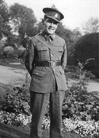 Figure 1: Artificer Sergeant Major P. K. Sartory about to go to India
In 1942 he was posted to India, where he served for 3 years as an instructor at the Government of India’s Instrument Mechanics’ Training Centre, Hindupur, which was staffed by officers and technical NCOs from the Royal Electrical and Mechanical Engineers (REME) and the RAOC. [1]
By the end of the war, Peter Sartory was an accomplished mechanic with an innovative nature and John Bunford was a trained accountant and businessman, so they were an ideal partnership to start a new company. They had worked together before the war and were both directors of Superma Ltd, a hairdressing equipment manufacturer jointly formed by their parents in the early 1900s. Space was available at the Superma factory for the new venture, and with the encouragement of many of the leading figures in microscopy, especially the firm of Flatters & Garnett who agreed to stock and promote their items, they were ready to proceed.
The formation of the company
In 1949 Sartory Instruments Ltd acquired the assets of R. S. Alldridge Ltd. [2] [3] This company started life as Chapman & Alldridge Ltd, who manufactured microscopes and accessories in the 1920s, it went into liquidation in 1928, R. S. Alldridge acquired the remaining assets from the liquidator and continued the business as R. S. Alldridge Ltd. Following his death the company struggled on for a bit but was no longer viable. It is probable that Sartory Instruments bought the company to acquire the machine tools and fine instrument lathes they owned, because the new company did not continue making any Alldridge equipment but designed and manufactured a completely new range of products.
A quote from an early product catalogue shows that this was a deliberate policy;
“Under the earlier management, prior to 1939, the main production had been that of Microscopes and Accessories. The present Directors being actual Microscopists their policy will be concentration upon Microscopes of specialised types, ancillary apparatus and scientific instruments for special purposes.
Accumulated experience as microscope users enables the Directors to offer instruments in which – as will be shown by the following pages – the requirements of the Microscopist have been noted, new solutions employed, and the resultant designs offer convenience, rigidity, simplicity and efficiency.
SARTORY INSTRUMENTS are not mass-produced, they incorporate the high standard of workmanship and precision of movement associated with the highest traditions of British craftsmanship, combined with the standardisation and interchangeability of machine production.” [3]
In reality, the directors’ microscopical experience was confined to Peter Sartory; John Bunford never had any interest in microscopes. He was finance director of Superma Ltd. and managed the finances of Sartory Instruments as part of his day to day activities.
The company was only active for 14 years; it started trading in 1949 from the Superma Ltd address; 7 Steele Road, Chiswick, London W 4 and continued at that address until 1962 when Superma was sold to The Sanitas Trust Ltd. They ceased manufacture in early 1963 and Sartory removed the machine tools and remaining stock of lenses and unfinished parts to his home workshop. The company was formally struck from the companies register and dissolved in 1968. [4]
Two other addresses appear on company literature, Newton Works, Bedford Ave, Perivale, Middlesex and 223 Acton Lane, Chiswick, London W4 but I am unable to ascertain why or what significance they had.
The company advertised in the School Science Review, Nature and very regularly in The Microscope during the 1950s; the first advertisement for the improved design Riddell-Stephenson Dissecting Microscope with “A new optical system” was placed in the March–April 1951 issue (volume 8 no. 6) [Fig 2]
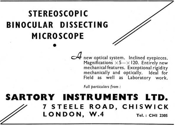 Figure 2: Advertisement from the journal The Microscope for May–June 1950
Unfortunately no trading records or account books survive and there is no record of the number of employees but I do not think that there were ever many. In the late 1950s, during the school holidays, I used to visit the Steele Road premises once a week to be given some basic workshop training by Jim Buckingham, the chief instrument mechanic at Sartory Instruments and at that time there was only him and an apprentice in evidence. A sales representative was also employed.
The Products
The company’s products seem to fall into two categories; “bread & butter” items for schools, technical colleges etc. and more sophisticated, sometimes bespoke, equipment for laboratories. All items were well engineered and of excellent quality.
Basic Accessories
These consisted of simple mains powered bench lamps of several designs, small top light illuminators, simple dissecting stands, Cameras Lucida, an attachable mechanical stage to fit the Watson Service and similar stands and low-power achromatic objectives.
Simple Microscope Lamps
A Laboratory Bench Lamp with an articulated cylindrical body to accommodate up to a 240v/100w bulb was supplied with an optional 2″ × 2″ blue filter and iris diaphragm. [Fig 3]
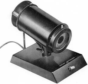 Figure 3: The Company’s first Laboratory Bench Lamp; the housing got very hot with prolonged use and it was soon discontinued.
A light cast alloy bodied student Bench Lamp was supplied to many schools and technical colleges, and proved very effective for student use. They were fitted with a 240v 60w pearl or opal bulb and required minimal set up [Fig 4]
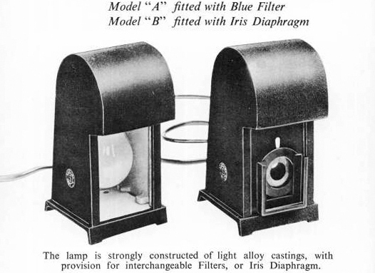 Figure 4: The Student Bench Lamps were a popular item with schools and technical colleges; especially the Model “A” which at £2 10s was over a pound cheaper than the Model “B” which needed to be more accurately aligned with the microscope
Two versions were offered; Model A; fitted with a large 5″ × 3″ blue glass filter and Model B with an iris diaphragm and provision for a 2″ × 2″ glass filter.
As a boy I used a Model A lamp with a Watson Service for many years and found it excellent, I still have it and when I want to quickly set up an old stand I often use it.
Top Light Illuminators
Small lamps using 6v 0.6w MES screw-in bulbs in a housing with a condenser lens and blue filter, mounted on articulated arms were also made. They were intended to illuminate small opaque objects. The base contained a small transformer to reduce the mains voltage. Single and double arm models were offered. They were very well engineered, the articulated limb particularly so, but the light output was somewhat feeble. [Fig 5]
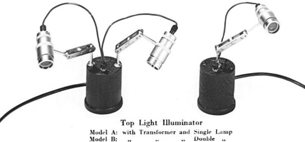 Figure 5: The top light illuminators sold in some numbers; they were light, small and due to the beautifully designed articulated arms were easy to set up and did not suffer from vibration. They were however somewhat dim
Attachable Mechanical Stage
This product was also aimed mainly at the school/technical college market and fitted on to any flat plane stage from 4″ to 6″ square; secured by two knurled clamping screws. It was smooth and precise in movement with no noticeable backlash. [Fig 6]
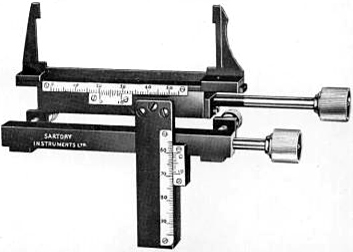 Figure 6: The attachable mechanical stage was another popular item, which worked well and was more rigid then many attachable stages because the vertical control knob was incorporated into the clamping system
Cameras Lucida
Two Abbe type cameras lucida were offered with different sized mirrors; one 3″ × 2″ and a larger 2¾″ × 4¾″ one, they also incorporated a swing-out neutral density filter. [Fig 7]
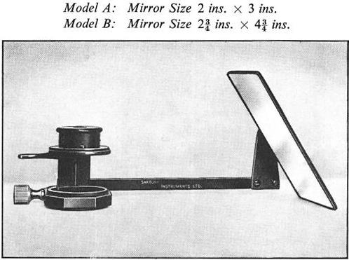 Figure 7: The Camera Lucida was of novel design with a larger than usual mirror, two sizes of mirror were offered
They were claimed to be an improvement on previous designs.
“This instrument has a modification consisting of Swan Cube in place of the Abbe Cube. By employing a half-silvered hypotenuse with a 3/16 inch (5 mm) clear aperture, it ceases to be sensitive to centring errors, and light is more equalised to within visual tolerances. In wide differences of illumination between object and drawing paper the use of one light modifier (neutral glass) will be found adequate, or slight adjustment of the substage condenser iris diaphragm will suffice.” [3]
Simple Dissecting Stand
A simple dissecting stand on a heavy base with a fully rotatable articulated arm that took different sizes of lenses was offered; 1¼″ diameter doublets of ×5, ×8 and ×10 magnification fitted into a sprung mount. This holder could be removed by slackening a locking ring and larger biconvex lenses of 2″ or 3½″ diameter could be fitted instead. [Fig 8]
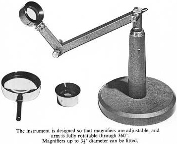 Figure 8: The Dissecting Stand had a heavy rigid base with a solid tubular support for the steel rod supporting the articulated arm giving it added rigidity
Simple Tank Microscope/Dissecting Stand
This ingenious device used the same doublets as the item described above, but was intended to stand in front of an aquarium as well as being used as a dissecting stand. Pupils could watch the development of frogspawn, for example, using this instrument. [Fig 9]
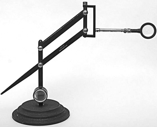 Figure 9: As well as a dissecting stand this ingenious stand could be used as a tank magnifier; note the holder for a different power doublet
Microscope Objectives
A range of low-power achromatic objectives were made (⅔″, 1″, 1½″, 2″ and 3″), the illustrations show a ⅔″ and a 2″ strain-free example. [Figs 10 & 11]
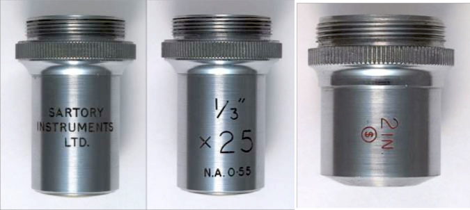 Figure 10 (left and centre): A number of achromatic objectives were offered; standard ones for student use and special ones with large diameter rear elements for the Riddell-Stephenson stereo instruments. This is a student’s ×25 N.A. 0.55
Figure 11 (right): A strain-free 2″ achromatic objective; possibly made to order, since objectives for polarising work were not part of the normal production
Laboratory and Bespoke Equipment
Riddell-Stephenson Low Power Stereoscopic Microscopes
Two versions of low-power stereoscopic instruments were offered using the same prismatic design. This was a variation on the design first demonstrated by J. L. Riddell in 1851 and reinvented by J. W. Stevenson in 1870. [5]
The Riddell-Stephenson design uses a pair of symmetrical prisms immediately behind the objective to reflect the light from one half of the aperture and direct it up a tube to a prism at the top which reflects the light again to the appropriate eyepiece, producing an image that is orthoscopic and erect. The design thereby produces an excellent (unexaggerated) erect stereo image. [6] [Fig 12]
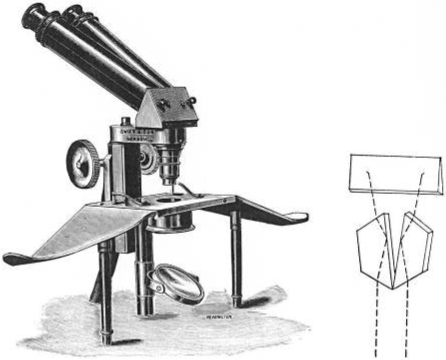 Figure 12: A 19th C. Riddell-Stephenson microscope made by Swift & Son with a sketch showing the light paths from the objective through the prisms. (From “The Light Microscope” by W. G. Hartley)
Sartory Instruments sales literature states:
“The binocular system employs a modification of the RIDELL [sic] and STEPHENSON designs. The pencil of light from the back lens of the objective is divided and partly erected by means of a pair of prisms set at the correct binocular angle. On emergence from these prisms the pencils are incident upon a reflecting element from which they are transmitted by rhomboid prisms to the eyepieces. As a result substantial increase of illumination is obtained. Special objectives have been designed having large aperture back lenses and working with the eyepieces listed to produce optimum results.
The system will work satisfactorily with any standard microscope objective of not shorter focal length than 1 in. (25 m/m) so long as the back lens is not too small. Any standard student’s eyepiece can be used.” [3]
A patent application relating to this improved design was made in November 1949 but I have not been able to ascertain whether it was granted. [7]
Stereoscopic Binocular Microscope with built-in illumination
This was the simplest version of this instrument; it had a sliding flattened-tube like housing with a locking nut in which the eyepiece tubes moved in order to adjust the inter-ocular separation and an illuminated tablet on which the specimen was placed, quite an innovation for the time. [Fig 13]
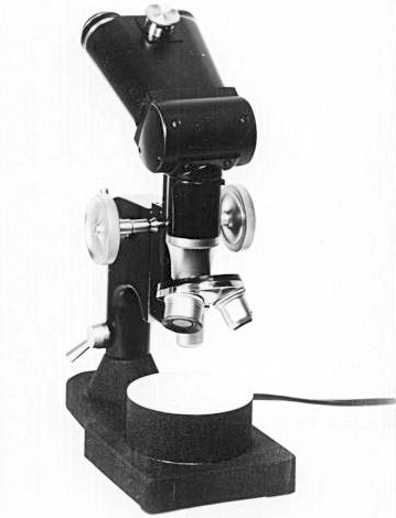 Figure 13: The stereo microscope with built-in illumination used a modification of Riddell’s design and a sliding eyepieces holder to vary the inter-ocular separation
Stereoscopic Binocular Microscope with inclined eyepieces
This extremely versatile instrument was offered in a number of types for different purposes and was a mainstay of the company’s production. The basic configuration [Fig 14], one of which is in the Science Museum’s collection, inventory no. 1997-372 [8] had a large flat base with a 4″ by 4″ clear glass specimen stage supported on 4 posts above a gimballed mirror. The specimen stage was held in a dovetailed mount and could be slid out for cleaning or to be replaced with a ground class or white vitreous one. Two clear Perspex hand rests were also provided. The stage with its supporting posts, the hand rests and the mirror could all be easily removed to allow the examination of larger specimens and the base had a 4½″ circular aperture into which stage plates or a special universal tilting stage for culture plates or Petri dishes could be fitted.
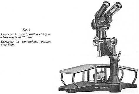
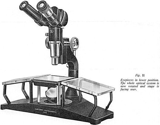 Figure 14: The Stereo Microscope (1) The Company’s major innovation; a well engineered instrument using the modified Riddell design to produce a bright, erect, stereoscopic image. The stage and Perspex hand supports were easily removed for sterilization or to accommodate large objects
The head was supported on a steel pillar with two loose extension collars. For dissections at bench level the head and focussing assembly could be rotated 180 degrees and one or both of these collars removed to allow the objective to approach the specimen. The base was sufficiently heavy to maintain the stability of the instrument when it was used in this way [Fig 15]
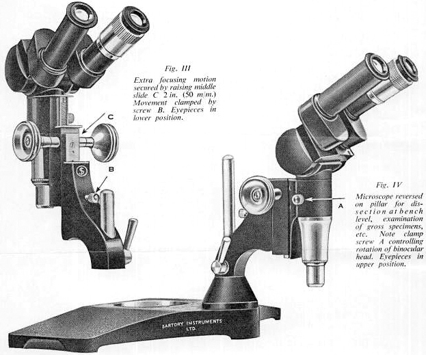
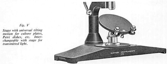 Figure 15: The Stereo Microscope (2) The microscope’s working distance could be varied in a number of ways and the substantial base made the instrument very versatile. Note the special universal tilting stage for Petri dishes etc.
A micro-manipulator stage was also available. [Fig 16]
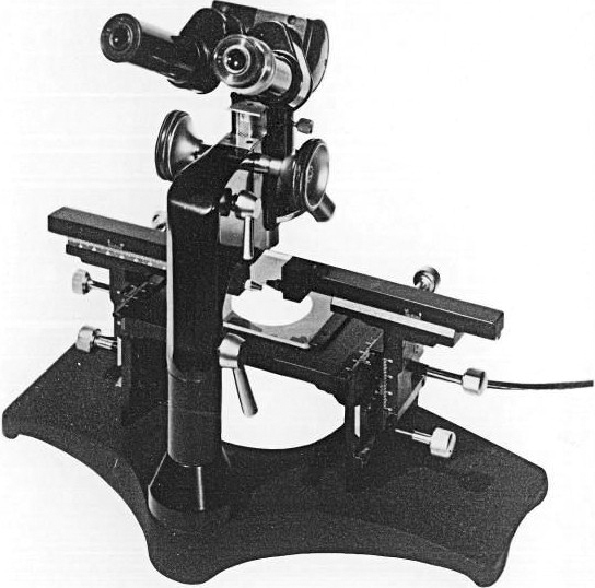
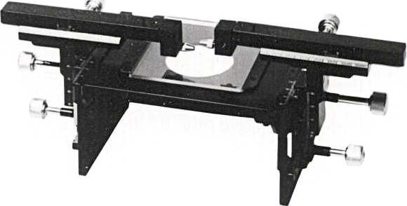 Figure 16: The Stereo Microscope (3) By the use of extension collars on the steel support post the microscope could be raised to a considerable height; in this case to accommodate the micromanipulator stage
The Sartory Universal Microscope Lamp
This was another well designed and popular item. A six volt transformer was housed in a heavy base with two steel columns; a long one mounted centrally to permit the use of the lamp up to 10″ above the bench and a shorter one at the periphery to enable the lamp to be used at a very low angle. A rheostat in the base controlled the brightness.
Two different lamp housings and collector lens assemblies were made, both with a centreable bulb holder to take a 30 watt flat “concentrated” filament bulb, a tungsten ribbon filament or (with an additional rectifier) a Pointolite.
In the cheaper version the collector with its iris diaphragm and filter was integral with the lamp housing and was mounted in a sliding tube for focussing the lamp. The whole was supported on a simple rod which was attached by a double clamp to either of the base columns. [Fig 17]
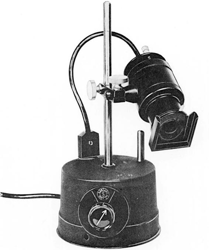 Figure 17: One of the company’s most successful products was the low voltage ‘High Intensity’ lamp; it was one of the first microscope illuminators to incorporate the transformer and rheostat into the lamp base
The more expensive and much better version had separate lamp and collector assemblies which were mounted on rails. [Fig 18]
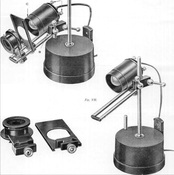 Figure 18: The more sophisticated ‘Universal’ lamp had an ingenious rail system to take saddles carrying the filter holders, the collector lens assembly, etc. The rails could also be slid within their support to balance the weight of the lamp assembly, reducing the tendency to tilt
“The clamp securing the lamp proper to the pillar is part of a solid cradle carrying parallel bars forming geometric slides. These bars can be moved along the cradle to balance the lamp according to the apparatus carried thereon, i.e., iris, condenser [collector], filters, etc, so overcoming vibration and the tendency to tilt.
The lamp (bulb) holder is mounted integrally with the end of the bars and provided with adjusting screws to centre the radiant when bulbs are changed. The HOOD [sic] is mounted independently and provided with an additional sliding tube to minimise stray light. The HOOD is narrow and tests show that with open ends the hood acts as a venturi tube, and cooling is more efficient. Mounted separately upon saddles with geometric bearings are a PLAIN SLOTTED CARRIER [sic] for acid etched, ground or opal glass, CARRIERS FOR FILTERS [sic], Lamp condensers.
The Lamp is truly UNIVERSAL [sic] in that [it] can be … employed for illumination by transmitted light, use with vertical illumination, dark ground illumination, top lighting of opaque objects, spot illumination of delicate dissections.” [3]
One of these lamps originally presented to the Quekett Microscopical Club by Peter Sartory is in the Science Museum’s collection, inventory no. 1990-163 [9]
The cheaper version was still being offered for sale by Flatters & Garnet in their ‘MIKROPS’ catalogue published in December 1963 and was substantially cheaper than the more bulky lamps of Baker, Beck, Swift and Watson also listed [10] [Fig 19]
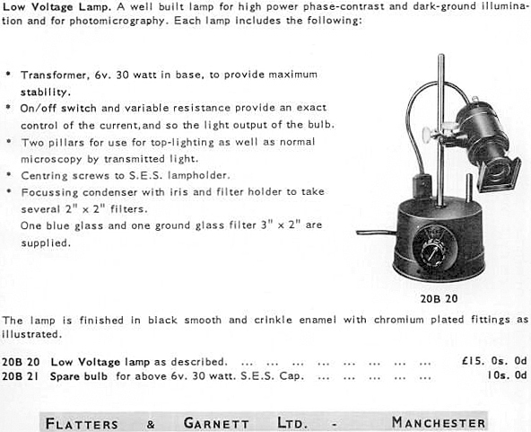 Figure 19: The lamp was still being offered for sale by Flatters & Garnet in December 1963, some months after the company had stopped production
Sartory Petri Dish or Culture Plate Searcher
This ingenious apparatus could be fitted to any microscope with a plain stage and allowed the culture plate or dish to be systematically examined. [Fig 20]
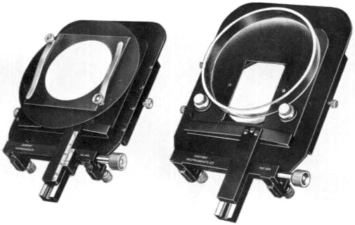 Figure 20: The patented Petri dish and culture plate searcher had rubber tread mounted revolving posts, which allowed the dish to be rotated during examination
“By means of the vertical movement effected by rack and pinion a series of areas from centre to the margin can be systematically selected. The posts are provided with rotary rubber treads providing adequate friction when the microscope is inclined, thus the culture plate can be rotated and the successive concentric circles together with the vertical motion ensure complete coverage of the area” [3]
It was supplied with or without a vernier scale for the vertical movement.
A British patent no. 689174 was issued in 1950 for this device. [11]
Micro-Projection Apparatus
A trade card showing this apparatus is in my possession; unfortunately I have no other information regarding it. [Fig 21]
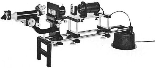 Figure 21: A trade photograph exists showing this robust micro-projection apparatus; note the holder for a heat filter and the flip-out eyepiece prism
Silica Gel Eye Tube Caps
Screw top pots with a drilled base, lined with porous paper and filled with silica gel were offered. They were intended to be used to inhibit mould growth (replacing the eyepieces) when instruments were used and stored in tropical or other damp environments. [Fig 22]
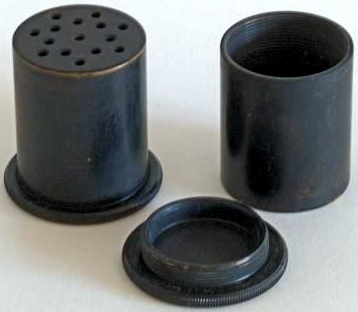 Figure 22: Silica gel pots, which could be used to replace the eyepiece to reduce damp in the tube and inhibit mould growth during storage
When I take my microscope ‘under canvas’ or on yachts I still use a pair.
3″ × 1″ Double Coverslip Slides
These are listed in a sales price list but I am unable to find any further information other than a mention in a Ministry of Agriculture technical bulletin issued some years after the company ceased to trade referring intriguingly to Sartory Instruments aluminium double-coverslip slides. [12] It is possible that these are the opaque specimen slides mentioned below.
Opaque Specimen Slides
The company did for a time supply single and double cavity card mounts with an aluminium holder and 3″ × 1″ glass slip cover for examining opaque objects, especially foraminifera, allowing easy comparison of two specimens but these are not listed in any literature that I have seen, unless they are the ones above.
Abbe Illuminators
Simple, cheap, two lens Abbe condensers with removable top lens, iris diaphragm and filter holder were also made and sold in some numbers; however they had no logo engraved on them.
Price Lists
I have in my possession two undated price lists; one issued with the sales brochure from which the above quotations are taken and a later (higher priced) list showing the 223, Acton Lane address. [Fig 23]
It is interesting to note that the price of the High Intensity Lamp jumped 20% in 9 months from £10 10s in March 1954 to £12 12s in January 1955 [see appendix] and that it cost £15 0s 0d by 1963.
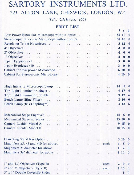 Figure 23: An undated price list, probably from the mid 1950s, showing the cost of the company’s standard items
Sartory Instruments was also a contractor to the Ministry of Supply (M.O.S.), I have been unable to ascertain what specific military equipment they supplied but I remember being told as a boy that the company made parts for gun-sights and rangefinders. Following my father’s death a number of boxes containing Sartory Instruments materials, lenses and instrument parts came into my possession including a large number of small, metal mounted, glass discs with engraved cross-hairs that seem to be intended for use in some sort of sighting apparatus. [Fig 24]
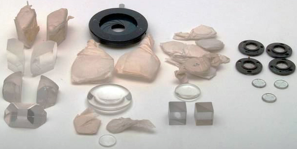 Figure 24: Samples of the various prisms, lenses and other items, some still in the paper wrappings from the supplier, left over when the company was dissolved. From the left; different prisms from the Riddell-Stephenson stereo; An iris assembly and lenses for the Abbe Illuminator; Lenses for the top-light illuminator with the Swan cubes with the half-silvered hypotenuse with a 5 mm clear aperture for the Camera Lucida below; Cross-hairs (mounted and unmounted) for some sort of sighting equipment, probably an optical gun-sight.
Conclusion
In spite of the quality and ingenuity of the equipment made, I don’t think the company was ever really profitable. It was already struggling by the mid 1950s and was something of a ‘labour of love’ for Peter Sartory. After his death, John Bunford told me he was “delighted to let Peter play with microscope equipment manufacture”, leaving him to run Superma [by implication the real business].
A letter from Peter Sartory to Michael Salmon, in response to a request for a catalogue and price list, dated 19th October 1955 reads;
“We are not making a great number of scientific instruments at the moment, since the alteration in the method of purchasing by Government, and the hire of instruments to students, has rather killed the market, although we are making an improved type of Stereoscopic Binocular Microscope, which is better than the one I showed at the Quekett some time back.
We are making the usual run of High Intensity Lamps, of which you have I think already seen models, but we are chiefly occupied in M.O.S. Contract work on specialised instruments.
We have not got an up-to-date list, although I send herewith a collection of picture postcards showing some of the instruments. If there are any in which you are interested I shall be delighted to send our Representative along to wherever you wish, and let you have them for examination or to use for a short while.” [13]
It is sad that the company lasted for such a short period, but perhaps it was inevitable, the post war supply bubble was bound to be short lived, and my father was much more interested in the intellectual and engineering challenge of producing innovative equipment than in sales figures or profit; fortunately for microscopy his income from Superma Ltd allowed him to indulge that interest.
Acknowledgments
I would like to thank Brian Bracegirdle for his help in preparing this paper and for encouraging me to write it in the first place. I would also like to thank Steve Gill for his invaluable assistance in trawling the internet to find much of the company background information, patent applications etcetera.
References
1. ANON, “A Career with a Future” an undated 16 page Government of India Department of Labour recruitment brochure for the Instrument Mechanics Training College Hindupur, as well as describing life at the college in some detail it has a picture of the military staff. ASM Sartory amongst them.
2. BRACEGIRDLE, B., Notes on Modern Microscope Manufactures. Oxford: The Quekett Microscopical Club. 1996. Page 64. The information was taken from the forward to an undated Sartory Instruments Sales Brochure. (See ref [3] below) No official record of the company’s formation has been found.
3. SARTORY INSTRUMENTS LIMITED, Stereoscopic Binocular Microscopes (low power) Microscope Lamps Microscope Accessories. London: [no date] A 14 page well illustrated sales information brochure probably issued in 1950 contains much detail about the company’s products and ethos. I have quoted extensively from it.
4. The London Gazette of 8th November 1968 contains the following: Notice is hereby given, pursuant to section 353 (5) of the Companies Act, 1948, that the names of the Companies mentioned in the two lists hereunder have been struck off the Register. Such Companies are accordingly dissolved as from the date of the publication of this notice.
Sartory Instruments Limited
5. FERRAGLIO, J., The Riddell-Stephenson Binocular Microscope, Journal of the Microscope Historical Society, 2008, 16, 1–24
6. HARTLEY, W. G. – The Light Microscope, its use & development. Oxford: Senecio, 1993 see pp. 118–121
7. SARTORY, P. K. and SARTORY INSTRUMENTS Ltd., Improvements in and relating to microscopes. 1950, British Patent Application GB19490029794 19491110, 10 November 1949
8. BRACEGIRDLE, B., A Catalogue of the Microscopy Collection at the Science Museum, London, CD-ROM, Little Imp Publications, 2005, Stereo Binocular Stand by Sartory, #26/134
9. BRACEGIRDLE, B., A Catalogue of the Microscopy Collection at the Science Museum, London, CD-ROM, Little Imp Publications, 2005, High-Intensity Lamp by Sartory, #36/18
10. FLATTERS & GARNETT LIMITED, Microps Microscopical Accessories. Catalogue 2/H. Manchester. August 1963. see pp. 4–6
11. SARTORY, P. K. and SARTORY INSTRUMENTS Ltd., Improvements in and relating to microscopes. 1950, British Patent Application GB19490024987 19490929, 28 September 1949 GB Patent 689174.
12. TECHNICAL BULLETIN-MINISTRY OF AGRICULTURE, FISHERIES AND FOOD, Issues 1–6 – Page 38 (1976), Suppliers of apparatus: Aluminium double-coverslip slides, Sartory Instruments Ltd. 7 Steele Road, Chiswick, London W 4
13. SARTORY, P. K., Letter to Dr M. Salmon in the author’s personal archive.
Carel Sartory
10 rue du 19 mars 1962
87210 LE DORAT
France
Appendix – Advertisements in The Microscope & School Science Review
Advertisements in The Microscope 1951 ~ 1955
Volume 8 no. 6 [March–April, 1951] page 164 A new design Camera Lucida
Volume 8 no. 7 [May–June, 1951] page 192 Stereoscopic Binocular Dissecting Microscope; no image
Volume 8 no. 8 [July–Aug, 1951] page 218 Stereoscopic Binocular Dissecting Microscope
Volume 8 no. 9 [Sept–Oct 1951] page 248 Stereoscopic Binocular Dissecting Microscope
Volume 8 no. 11 [Jan–Feb 1951] page 304 Adjustable Magnifier Stand
Volume 9 no. 1 [May–June 1952] page 28 Top Light Illuminator
Volume 9 no. 4 [Nov–Dec 1952] page 112 Sartory New Low Voltage Projection lamp
Volume 9 no. 7 [May–June 1953] page 196 Sartory Universal Mechanical Stage
Volume 9 no. 10 [Nov–Dec 1953] page 280 Sartory Universal Mechanical Stage
Volume 9 no. 12 [March–April 1954] page 328 Sartory High-Intensity Microscope Lamp (£10 10s)
Volume 10 no. 5 [Jan–Feb 1955] page 140 Microscope Bench Lamp
Volume 10 no. 7 [May–June 1955] page 196 Sartory High-Intensity Microscope Lamp (£12 12s)
Advertisements in The School Science Review
Volume 31 (June 1950) – the earliest advertisement found
Attachable stage, Lamps, Camera Lucida & “A new Binocular dissecting Microscope” [sic]
The company also advertised in Nature in 1951
This article was originally published in the Quekett Journal of Microscopy, 2011, 41, 397–409