

Zeiss “jug handle” microscopes
By Tony Jarratt
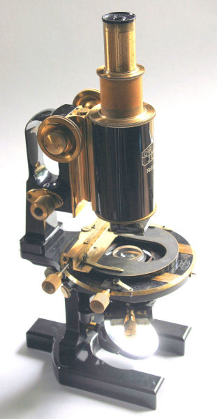
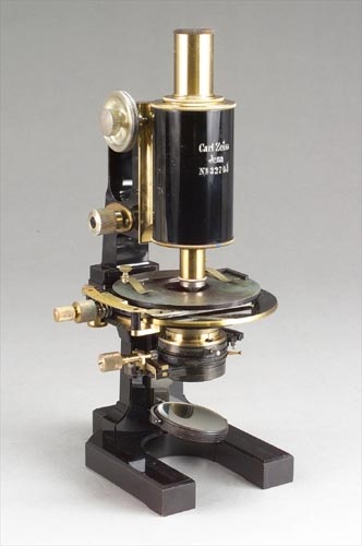
This short paper has been written with the purpose of comparing two Zeiss “Jug Handle” microscopes, which I have in my possession. One was produced in the early 1920’s and the other at the very end of the 19th century. The former is a “standard Jug Handle”, whilst the earlier stand is one of the rarer “Photo-micrographic” stands. The two instruments are illustrated below.
![]()
![]()
Serial numbers
The standard Jug Handle microscope: Stand number 82246
The serial number places the production of this instrument in the early years of the 1920’s – most likely 1922/1923. It is therefore a little over 20 years later than the second instrument shown below.
This microscope is fitted with a circular rotating stage which, in turn, is fitted with a standard X–Y mechanical slide holder. The stage can be centered.
X and Y movements are controlled by two separate screws with milled heads.
The rise and fall sub-stage has an Abbe condenser in a centering holder, an iris in a rotating traversable holder and a plano/concave mirror. This mirror is fitted by means of a plug-in rod to the bottom of the rack mechanism. Its vertical height relative to the condenser and iris, therefore, varies.
The sub-stage
 The Sub-stage – 1 – condenser and iris in normal position
 The Sub-stage – 2 – iris is swung out of optical path
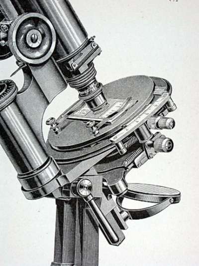
The Photo-micrographic stand: Stand number 32704
 This Photo-micrographic stand is recorded in the Zeiss Production Book as being ‘completed’ on December 15th 1899 and as delivered to London on 2nd February 1900. This makes it one of the last microscopes to be produced in the 19th century.
This instrument is also fitted with a circular rotating stage, but this is non-centering. It also has slide clips instead of the mechanical slide holder.
In this case X and Y movements (of the upper part of the stage) are controlled by two coaxial screw threads, again with milled heads.
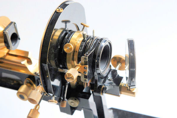
The rise and fall sub-stage is more complicated that the one shown above. It has a (non-centering) Abbe condenser, fitted on a swing-out arm and two irises. The lower one is fitted in the same rotating traversable holder, whilst the top one is a domed iris, which can be operated only when the condenser is swung out of the optical path. The mirror is fitted to the bottom of the rise and fall mechanism. Its vertical height relative to the condenser and iris is, therefore, fixed.
The stage controls
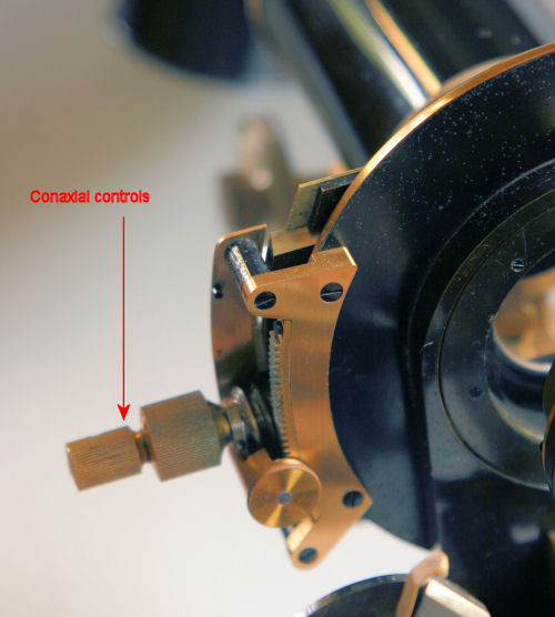 Stage movement coaxial controls
The sub-stage
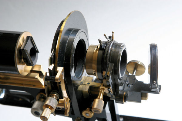 The Sub-stage – 1 – condenser and both irises in normal position
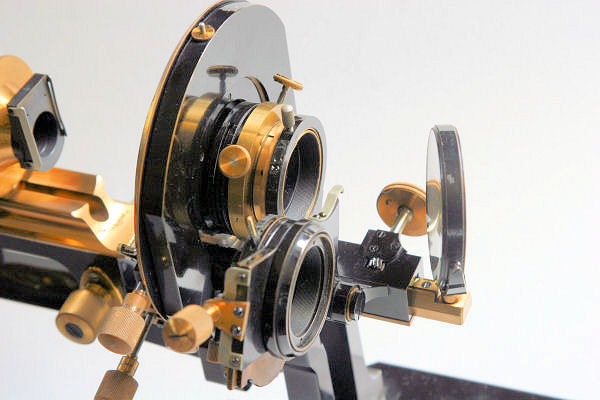
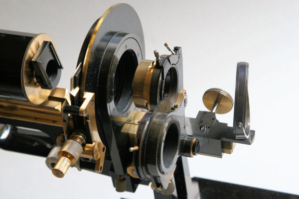 The Sub-stage – 2 – lower iris swung out of optical path
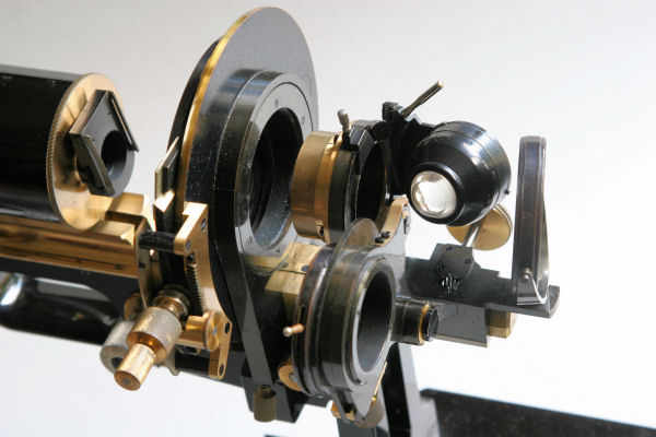 The Sub-stage – 3 – lower iris and condenser swung out of optical path
 The Sub-stage – 4 – another view, with the lower condenser and iris out of the optical path
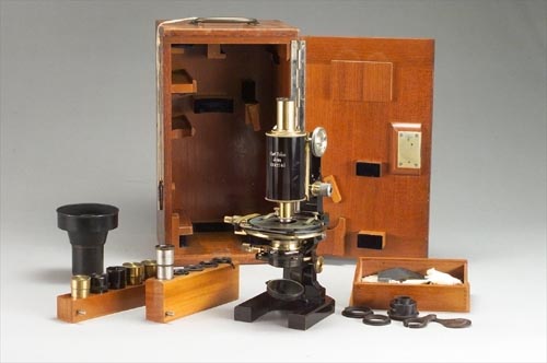
The accessories and case
The image below shows the Photo-micrographic stand with its accessories and case. The case is fitted with several holders and clips for the accessories and these are all ‘full’, thus indicating that the set retains all items as “originally supplied”.
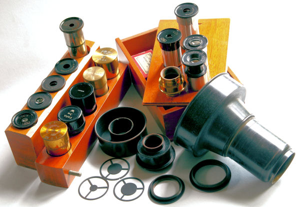 Close-up of accessories
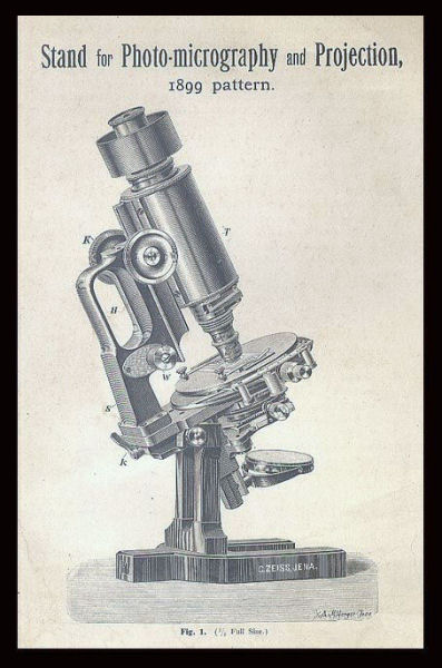
The catalogue
The image below shows a scan of the front page of a Zeiss catalogue dated 1899 – depicting the instrument in question. It describes the instrument as being for Photo-micrography and Projection.
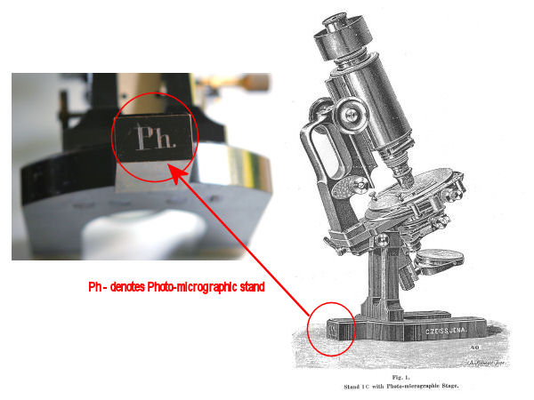
The foot engraving
The image below shows the “Ph.” engraved on the foot that identifies the Photo-micrographic stand.
Typical configurations for the Photo-micrographic stand
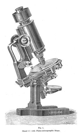 The Microscope
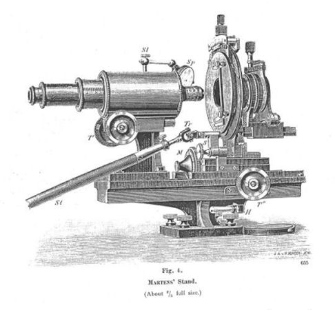 Mounted on Martens’ Stand
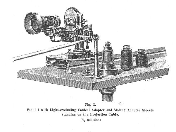 On the Projection Table
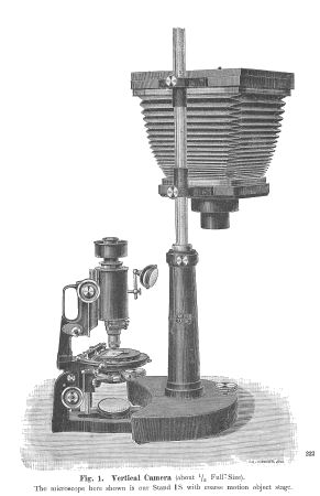 With simple Vertical Camera
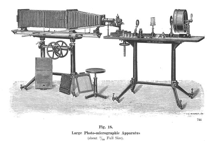 With Large Photo-micrographic Apparatus
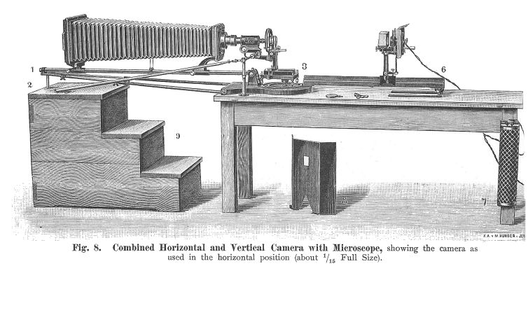 With Horizontal Camera
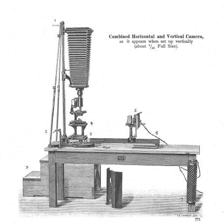 With Vertical Camera
The unusual feature
This Photo-micrographic stand, which is a variation on the Stand 1C, is supplied with a number of attachments used for “linking” a camera to the microscope. As stated above, it has a normal sub-stage with lower iris in a rotating and traversing mount, swing out Abbe condenser, and a domed upper iris, which can be used when the condenser is not in place.
All other controls and features are as would be expected for an instrument of this type and date, but the microscope does possess an unusual feature – the reason for which (to date) no-one has been able to explain satisfactorily (including the archivists at Jena).
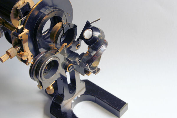
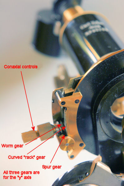
This feature is the circular rotating “Photo-micrographic stage”, with its concentric X–Y controls and vernier scales. See picture below.
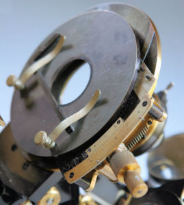
The Photo-micrographic stage
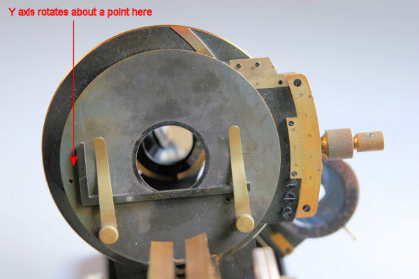
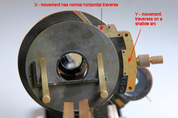
As can be seen, the X-axis movement of the stage is quite “normal” – it moves, as would be expected, along a 180 degree (E–W) direction. Total length of travel (X) is 10 mm. However the Y-axis does not move at 90 degrees to this (N–S) – rather it moves instead along a shallow arc with its centre of rotation towards the left hand side of the top layer of the stage. Total length of travel (Y) is 15 mm.
At first sight, this ‘curved’ movement might appear to be a way of reducing cost when producing the stage. Cutting the ‘rack’ part of the gear, as part of a circle, so that it matches the outer circumference of the stage, would appear to make sense.
However this isn’t the case – the arc of the rack and outside curve of the stage are different. The ‘Y’ movement arc is much shallower than that of the stage. So that idea doesn’t work.
A possible clue as to the reason behind the design
An entry in the 1898 Zeiss catalogue (kindly scanned and sent to me by Brian Davidson) reads as follows: –
“Photo-micrographic Stand (Fig 17).
This stand is in point of size and general arrangement similar to Stand 1a.
The round rotating stage is of solid brass and has a diameter of 100 mm = 4 in. It may be moved in two directions at right angles to one another by means of two coaxial milled-heads H and V (Fig 17). The position of the stage reads off by verniers.
The mechanical stage of the above stand is constructed with a view to impart a very slow motion to the object so as to render it particularly suitable for the projection of a mechanical image on a distant screen. It’s solid construction admits, as in the case of Stand 1a, of the use of any kind of object-carrier, in particular, also of culture-plates and dishes.
The body-tube is very short and unusually wide so as to provide for the application of our Projection-lens of 70 mm focus. This stand may, with advantage, be used for ocular observation.”
Although these details are from the 1898 catalogue and refer to the model that just pre-dates the Jug Handle (the new design was introduced in 1898 in conjunction with the Berger fine adjustment mechanism), the general design of the stage is the same.
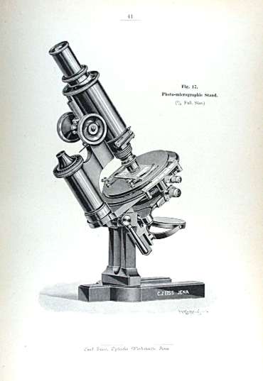 An image of the microscope
A close-up of stage as shown in catalogue
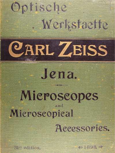
An image of the catalogue cover
If one is being pedantic, these details, as printed by Zeiss – aren’t strictly correct. They state that “It may be moved in two directions at right angles to one another…”. But they are not at right angles – one moves in an arc!
However, as noted above, both the ‘X’ and ‘Y’ axes do move very slowly – there is a far higher gearing in the movement when compared with the standard stage. One complete turn of the control knobs produces the following movements:
| Instrument | Movement along the X axis | Movement along the Y axis |
| Standard Jug Handle | 17.0 mm | 5.0 mm |
| Photo-micrographic | 0.5 mm | 2.0 mm |
As stated by Zeiss, this very slow motion allows the movement of projected images to be controlled very precisely – something that is obviously not possible with the standard stage. However, this does not explain the reason for having one axis move on an arc, and the construction of the coaxial screws and gearing seems to be overly complicated for the final result.
Overly-complicated construction
I would love to hear from anyone who might be able to suggest an explanation for this unusual design. Perhaps a “Quekett”, with an engineering background, would like to help?
Tony Jarratt – August 2006
All images on this page are Copyright © 2007 Tony Jarratt