

Theory of contrast control
The theory of contrast control in the microscope
Originally published in Quekett Journal of Microscopy (2000) vol. 38: 617–627
Jeremy Sanderson
Summary
This paper discusses the need for contrast in the microscopical image and how it may be generated and controlled. A subsequent paper will discuss the practical issues involved in aligning the microscope and achieving different contrast-enhancing methods.
Introduction: why contrast is needed in the image
The human eye perceives only differences in wavelength (as colour) and amplitude (as brightness) of the light reaching it. The eye cannot see differences in the phase relationship between different beams of light, nor can it discriminate the electric vector component of the light wave, nor the plane of polarisation. Very few microscopical specimens inherently possess sufficient natural highly-saturated colour to allow them to be studied without extra treatment. Because of their structure, most specimens produce phase changes, rather than amplitude changes, in the light passing through them. To see the phase relationship, or the plane of polarisation, of the light waves to generate contrast in the image, these invisible characteristics must be converted to differences in brightness or colour, to produce adequate contrast in the image.
Contrast is defined as a juxtaposition of form and colour to show a difference between them. Visibility is that which can be perceived by the eye. Both definitions need to be taken together in order to define “contrast” as used in microscopy. Any microscopical image comprises the background illumination and the image of the specimen. The juxtaposition referred to is between the image of the specimen and the background illumination. We manipulate the contrast in the microscopical image in order to optimise visibility.
It is easier to see a black cat against a snowy landscape than it is to see a white one; the former will be visible over a greater distance – even though they are the same size and the amount of detail potentially capable of being resolved is the same. Moreover, the black cat will still be seen further away than a tabby, which occupies an intermediate position between the black and white animals. Very often, particularly in biological microscopy, we are faced with the problem of maximising both the visibility and detail of specimens lacking in contrast, but often have to settle for a partial solution akin to the case of the tabby cat. This shows the importance of selectivity – we need a least some regional differences of contrast within the object to discern detail. Detail is not seen in the homogeneously black or white cats, but can be seen in the tabby, even though this cat is of intermediate contrast compared to the other two cases.
The theoretical basis of contrast
The threshold value of visibility when the human eye can just discriminate a difference between the object and the background is taken to be 2%, when no bright or dark separating boundary is present around the image of the specimen. The value of 2% contrast quoted [1] assumes first-class optical components, microscope alignment and visual acuity. As the limit of resolution is approached, the need for adequate contrast becomes more significant since the overall contrast in the image is reduced. In practical terms, this reduction in contrast generally arises when studying the detail of minute structures within the body of the specimen.
The table shows the percentage contrast achieved with different specimens and different contrast-enhancing techniques. These figures are only a guide, for the background and image intensities will vary over the entire field of view, and therefore the degree of contrast in the image will also vary over the field of view. Amphipleura pellucida has been included because it exhibits almost no contrast when examined with transmitted light using bright-field microscopy. Many people new to microscopy use the condenser iris diaphragm to introduce contrast into the microscopical image mistakenly believing that doing so produces a better image. However, these figures show that the degree of supposed improvement is not as great as imagined. Unstained cells have a very low percentage contrast of 2–5%, and closing down the condenser iris diaphragm only introduces 2% to 10% more contrast.
Contrast is not inherently dependent upon the structure and size of the specimen, but it does depend upon how the specimen interacts with the illumination and how the light leaving the specimen is further modulated and received by the receptor (usually the eye). Other factors to consider include the structure, size, shape and orientation of the specimen, as well as the wavelength and intensity of the light used to illuminate the specimen and form an image.
Table showing contrast achieved with different methods of contrast enhancement.
| Threshold level for the eye | 2% |
| Amphipleura pellucida, test diatom (transmitted light, bright field, no contrast enhancement) |
3% |
| Unstained cells viewed by bright field, transmitted-light | 2–5% |
| Cells viewed with condenser iris closed | 5–10% |
| Polished & etched metallurgical specimen, reflected light | 5–15% |
| Cells viewed by phase-contrast, transmitted light | 10–15% |
| Section of paint viewed by interference contrast | 15–20% |
| Stained tissue section viewed by bright field | 20–25% |
| Tissue section viewed by interference contrast | 20–40% |
| Diatom sample viewed by interference contrast | 30–40% |
| Diatom sample viewed by analogue video enhancement | 40–50% |
| Deeply-etched metallurgical specimen, reflected light | 50–60% |
| Rock thin section viewed under crossed polars | 40–70% |
| Birefringent crystals viewed with polarised light (with good extinction of the crossed polars, this value can reach 90%) |
40–70% |
| Cells viewed by dark ground | 45–70% |
| Fluorescently-stained cells | 60–80% |
Practical control of contrast in microscopy
In any compound microscope, proper control of three fundamental parameters governs its use. They are: resolving power, contrast and magnification, in that order of importance. To the lay person, microscopes are about magnification, but this is required merely to present the resolved detail to the eye. Nevertheless, there are upper and lower limits to the useful range of magnifying power, and these limits are determined by the acuity of the eye or other receptor.
The light microscope has been developed to a level of performance limited only by the physical laws of diffraction and the limits imposed by using visible radiation for illumination. Resolving power is thus designed into the microscope by the manufacturer at a maximum limit, according to the quality of the objective. The limits imposed by the design of the microscope on resolving power and magnification means that only the second fundamental parameter, contrast, remains within the direct control of the microscopist. Contrast can therefore be altered to examine many different types of specimen, or a single specimen can be examined by different methods of contrast enhancement to elicit the maximum information about it.
Contrast may be improved by placing suitable apertures or filters within the optical path, either in the illuminating system alone (dark-ground or Rheinberg illumination), or in conjugate planes in the imaging system (e.g. for phase contrast, differential interference contrast or polarised light microscopy). The condenser provides a conveniently-sized and controllable instrument for altering the illumination and/or inserting the necessary apertures or filters for contrast enhancement in the image. When it is necessary to insert apertures or filters within the objective to modulate the light forming the image, this is generally done by the manufacturer.
A condenser is the one major optical component which can be fully adjusted by its user, and it determines both the type and quality of the illumination, and also the visibility of the image. The condenser must illuminate the specimen correctly so that the light collected by the objective forms a meaningful image. To ensure this happens, the microscope must be aligned according to the principles of Köhler illumination. This faithfully provides a high-quality image, and allows for controlled manipulation of the light to alter contrast in the image. It is often impossible to set up other forms of contrast enhancement unless the condenser has first been correctly aligned to give a good image with bright-field illumination.
The interaction of light and matter – generating contrast in the image
Light interacts with matter in six ways:
- Absorption, reflection and transmission of light by the specimen;
- Diffraction of light by the specimen;
- Refraction of light by the specimen (other than by polarisation);
- Phase changes;
- Polarisation of light by the specimen; and
- Fluorescent light emitted by the specimen upon energizing by shorter wavelength light.
Besides these specimen-light interactions, contrast may also be enhanced by manipulating the source of light, or the recording device. There are thus three major ways of controlling contrast in the image:-
a.) Manipulation of the specimen-light interaction (e.g. using dyes or absorption stains within the specimen, or filters in the illumination. Exploiting phase changes or the birefringent properties of the specimen to polarise light or by using fluorochromes). This involves using the objective and/or the condenser.
b.) Manipulation of the method of illuminating the specimen (e.g. oblique illumination or dark-ground illumination) by using the condenser alone.
c.) Manipulation of the recording device or storage medium (e.g. by electronic means or by changing the photographic material). This category involves those contrast enhancement methods that act upon the image after it is formed by the microscope but before it reaches the eye.
Each of these man-made groupings is not mutually exclusive, and the different ways of generating or modulating contrast in the final image is limited only by the ingenuity of the microscopist. A good example is Rheinberg illumination, where diffraction effects are combined with selective absorption of light in certain parts of the specimen, to generate contrast from both differential colouring within the image and changes in light intensity between the image of the specimen and the background.
1. Absorption, reflection and transmission of light by the specimen
Objects transmit or reflect some light and absorb the remainder. When they selectively absorb light they appear coloured because we then only see the remaining wavelengths of the visible spectrum. This applies whether the object reflects or transmits the light falling upon it, although staining using coloured dyes is used principally with transmitted light. Filters provide the microscopist with an easy and inexpensive way to manipulate contrast due to the absorption of the illuminating light. However, filters cannot of themselves generate contrast unless the specimen itself is differentially coloured. A filter of complementary colour to that of the specimen will enhance contrast. Conversely, contrast is reduced, but the detail of differentially-coloured inclusions within the body of the specimen is enhanced, when a filter of the same, or similar, colour to the specimen is inserted into the path of the illumination.
Filters are also useful in photomicrography when the sensitivity of the emulsion to different wavelengths of light may be exploited to enhance contrast in the image. Colour may be generated optically in the image, as a result of the structure of the object. This is best seen when birefringent specimens are illuminated with polarised light, and this is dealt with below.
When placed on the optically blank background of an empty glass slide, a light-absorbing specimen forms an image possessing inherent contrast. Likewise, a specimen of differing reflectivity mounted on, or contained within, a mirror-polished surface will also form an image by reflected light. Parts of the specimen such as grain boundaries may be selectively enhanced by chemically etching the surface of the polished material. This introduces sufficient inherent contrast to study the structure of the polished material. In this case, differences in reflectivity between adjacent areas of the sample may well be small, and careful control of stray light in the imaging system is required so that what little inherent contrast exists is not reduced.
2. Diffraction of light by the specimen
When a ray of light passes an opaque edge, it is bent into the shadow area. This bending of light is dependent upon its wave-like properties, and is called “diffraction”. It was demonstrated by Abbe to be essential to the formation of the image. “Refraction” refers to the bending of light as a result of its passage from a transparent medium of one optical density into another of a different density. As a result of the change in velocity, the ray of light is bent.
In either transmitted-light or reflected-light microscopy, the illumination forms the brightly-lit background against which the object is rendered visible. If the illumination is shone at such an angle that the light does not enter the objective, then the background will be dark. In this case, a bright image will be formed where the object scatters, or diffracts, light back into the objective. This can occur in either transmitted or reflected illumination. If the specimen also absorbs some of the light, the image will be coloured. Generally such colouration is complementary to that found in an image formed by bright-field illumination. A schematic diagram is shown below to illustrate the relationship between bright-field and dark-ground image formation.
3. Refraction of light by the specimen
When a transparent specimen is immersed in a fluid of the same refractive index (RI), it effectively becomes invisible. For this reason, mountants of high refractive index, such as Realgar, Pleurax and Styrax, have been used to prepare specimens of diatoms to render them highly visible. The greater the refractive index mismatch, the wider and more pronounced will be the edge formed between the image of a specimen and its background.
For many substances there is usually a change in refractive index according to the wavelength of light at which the RI is measured. This phenomenon is termed ‘dispersion’. If white light is used to illuminate a transparent particle, colour fringes may be seen at its edge when a narrow beam of illumination is shone at an angle to the optical axis. This effect is called the ‘Christiansen effect’. Dispersion staining is thus a contrast-enhancing technique which uses the ‘Christiansen effect’ to optically colour small transparent substances.
Particulate grains or crystals lend themselves best to colour contrast by dispersion staining. Other transparent substances may be too large for this technique, and yet neither possess birefringent properties which may be exploited by polarised light, nor have the ability to take up coloured stains and selectively absorb certain wavelengths of light. If these transparent specimens have a complex structure which scatters so much light that dark-ground illumination is unhelpful, then the only options available are those using phase contrast, interference contrast or a form of oblique illumination. All these methods depend upon the refraction of light by the specimen.
4. Phase changes
Light can be considered as a wave. Where two rays of light originate from a common source they are said to be “in phase”. If a transparent specimen is arranged to lie in the path of one of these beams, but not the other, it will alter the velocity of that beam. The two beams, which started out in synchrony – or in phase – will now be out of phase, and this difference is referred to as the phase difference between the two beams.
With a stained specimen there is a half-wavelength (½λ) phase difference between the undiffracted beam and those diffracted by the specimen. Interference of the two sets of beams leads to overall differences in amplitude, which can be detected by the eye as differences in brightness. Thin transparent objects, such as cells, introduce a phase difference between the two beams of only one-quarter wavelength (¼λ). What is required to render these specimens visible, is an artificial means of introducing an extra ¼λ phase difference between the diffracted and undiffracted beams, so that the eye sees the overall amplitude difference (due to interference) once the beams are recombined to form an image.
In phase-contrast microscopy the illumination is isolated using an annulus in the front focal plane of the condenser. An image of this annulus is visible in the back focal plane of the objective as a bright ring of light. A phase ring built into the objective at the back focal alters the phase of the undiffracted illuminating light may be altered without affecting the diffracted light. The optical path traversed by the undiffracted beam alone can now be selectively advanced (or retarded), and the necessary extra ¼λ phase difference between the two beams introduced before they recombine to form the image. The phase ring carries on it an absorbing layer which reduces the amplitude of the undiffracted zero order beam to match that of the weaker beams diffracted by the specimen.
In phase-contrast and dark-ground microscopy, the direct, illuminating, rays of light and those scattered by the object (which interfere to form the image) have been separated by the object. In the various forms of interference microscopy the beams are separated optically in the instrument by using polarised light. Specialised prisms, called Wollaston prisms, are inserted in conjugate optical planes in the condenser and the objective to split the light before the specimen and recombine it afterwards.
Differential interference contrast (DIC) microscopy is the most useful form for contrast enhancement, because the image does not suffer from any noticeable lateral shear due to the separation of the two beams being too small to be resolved, and therefore no ‘ghost image’ is seen partially superimposed upon the real image. Nevertheless, each point of the image is illuminated by two closely apposed beams, and a phase difference may exist between them depending upon the optical path difference introduced by the nature of the specimen. The contrast is described as differential (in the mathematical sense) because it results from the interaction of these two beams, and is a function of the rate of change of optical path difference across the object. The steeper the optical path difference at the structural boundary of a feature, the greater the contrast.
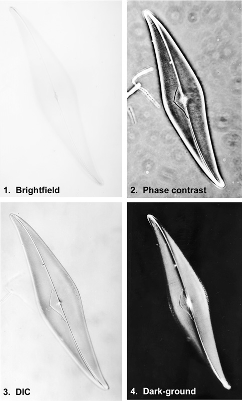
Figure 1. The diatom Pleurosigma angulatum imaged using four different methods of contrast enhancement with illumination by transmitted light.
1. Bright-field illumination, almost no contrast is seen.
2. Phase contrast. Contrast is improved, but the ‘halo’ surrounding the specimen and discrete refractile particles within the preparation, or on the surfaces of the slide, can obscure the image and make any form of measurement difficult.
3. Differential interference contrast. Ideal for measurement, DIC is not as widely available as phase contrast.
4. Dark-ground illumination, very high contrast. This method is best suited to thin specimens with a regular structure. Thick sections generally diffract the illumination to a greater extent, which gives rise to more stray light in the image.
5. Polarisation of light by the specimen
The velocity of light in isotropic materials, such as sodium chloride, is constant, irrespective of the direction in which the rays of light enter the specimen. Certain other materials are birefringent, or anisotropic, because their crystalline structure differs from one dimensional plane to another, and they possess two, or sometimes three, refractive indices.
Electromagnetic radiation, including visible light, vibrates in all directions perpendicular to the direction of travel when emanating from a source. A polarising filter (polar) transmits a single plane of light, absorbing the remainder. Where two polars (the first is being the polariser, the second the analyser) are arranged with their permitted vibration directions at 90° to one another, they are referred to as “crossed”, and no light will be transmitted unless an anisotropic specimen is placed between them. The anisotropic substance will split the plane-polarised light into two different, yet still coherent, rays, each with a unique velocity determined by the refractive indices of the specimen. These two coherent rays, arising from a common source, will recombine and will interfere when they leave the specimen. The optical path difference between the two rays depends upon the product of the birefringence (the difference between the refractive indices of the specimen) and the thickness of the specimen. The highly-saturated polarization colours seen are a result of the interference of these two rays once they are recombined. A compensator, such as a first-order red plate, intensifies these polarization colours.
If an anisotropic specimen is rotated within plane-polarised light and viewed without an analyzer, the contrast will change between two maximum and minimum values for each complete rotation. This is known as bi-reflection. Pleochroism, or dichroism, is a special case of bi-reflectance where the birefringent material shows a difference in intensity and/or colour according to the different wavelengths that are absorbed depending upon the orientation of the specimen to the single polar. This phenomenon is best seen in thin sections of crystalline minerals, such as biotite.
6. Interaction of the specimen with fluorescent light
Certain chemicals, when irradiated by ultra-violet absorb some of that energy in a specific manner and re-emit it as lower energy of longer wavelength, generally as visible blue or blue/green light. The process occurs almost instantaneously, and the emission is characteristic of the chemical structure of the specimen. The value of such fluorescent chemical molecules is twofold. First, the contrast is very high; just a few brightly self-luminous components can be seen against a dark, non-fluorescent background. Secondly, the fluorescent spectrum emitted is specific to the fluorochrome being illuminated.
Fluorescence does not occur solely with ultra-violet as the illuminant. Any short-wavelength high-energy light source is suitable, providing that it is sufficiently intense to excite the fluorochrome. If blue light is used for excitation, the fluorochromes affected will emit green light; if green light is used, the emission is generally in the visible red, and may extend into the far red spectrum.
Early fluorescence microscopes were based on a transmitted-light microscope stand with a dark ground illuminator. The fluorescent illumination was excluded from the objective, forming a dark ground, whilst the fluorescence emitted by the specimen was picked up by the objective to form a bright image on a dark background. In the mid 1970s, the introduction of the reflected-light microscope with a dichroic mirror revolutionised fluorescence microscopy, and the epi-fluorescence illuminator has now been almost universally adopted for this type of work. Not only is the image brighter (in direct proportion to the numerical aperture of the objective), but the system is also easier to align, and safer to use. A fluorescence epi-illuminator also allows an extra degree of freedom in contrast formation, as the transmitted-light path can be used to form a phase-contrast image of the specimen simultaneously.
Stray light
Besides these six groups of light-matter interactions which affect contrast in the image, the influence of stray light, or glare, is also important. Stray light does not contribute to image formation, but decreases the overall contrast in the final image. Stray light also prevents the use of the full aperture of either the objective or condenser aperture, and this is the reason why the illuminated field diaphragm and the condenser iris diaphragm are closed down slightly from the maximum aperture when aligning the microscope. Coated lenses improve matters, and it pays to ensure where possible that all internal surfaces are coated matt black to keep stray internal reflections to a minimum. Although the amount of light reflected at either an air/glass or air/water interface is only about 3%, the sum of light lost at each individual optical surface within a complex objective can amount to a serious reduction in contrast if stray light is not controlled.
It is in polarised light and DIC microscopy that stray light has the biggest impact on contrast. Light scatter due to surface dust or strain-birefringence on the lenses, imperfections in the quality of the polarising filters, and optical rotation of the light at multiple lens surfaces, all conspire to degrade cumulatively the extinction coefficient of fully-crossed polars, and reduce contrast. In dark-ground microscopy, because the method works by the image scattering light, any extraneous dirt within the preparation or on the surfaces of the slide and cover slip can also scatter stray light, and severely reduce the contrast in the image. The influence of stray light on image quality is thus particularly noticeable. A well-prepared dark ground specimen will exhibit 50–70% contrast, depending on its structure. If a smear of finger grease is deliberately left on the surface of the coverslip, the contrast can be reduced to a figure of 30% or less, quite apart from obscuring the structure and clarity of the image.
Manipulation of the illumination
For most purposes, transmitted-light bright field microscopy uses the full ‘solid’ axial cone of illumination supplied by the condenser. This is suitable for amplitude specimens (those which are stained or naturally-coloured), but not for transparent unstained phase specimens. If the edges of such transparent specimens are appreciably thick, and/or they are mounted in a medium of different refractive index, then they will exhibit some contrast due to refraction at the edge, as discussed above. If the edge of the structure is inclined to the optical axis of the illumination, then the contrast can be further enhanced. As an extension of this, if the illumination is tilted before a dark-ground image is formed, oblique illumination will result. Generally, uniaxial oblique illumination is used by restricting the light to one direction, or azimuth, but annular ‘hollow cone’ illumination is also possible. With uniaxial illumination, regular features (such as the punctae on diatom frustules) will be more pronounced when they lie perpendicular to the axis of illumination, and less visible when lying along that axis.
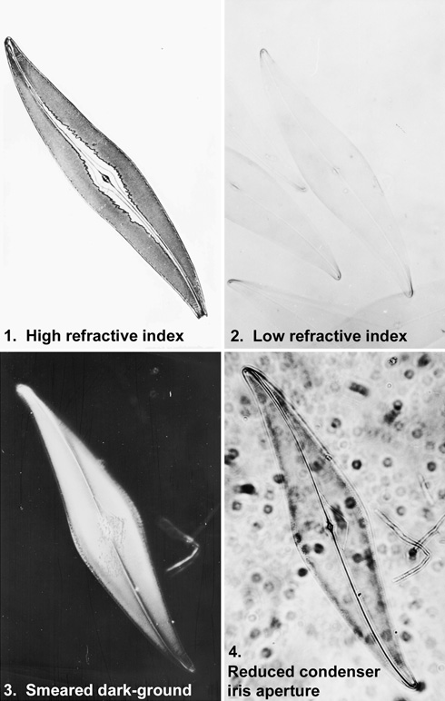
Figure 2. The effect of a changing the conditions by which the image is viewed.
1. The effect of high refractive index, transmitted-light bright field. The mountant in this preparation has broken down; there are localized areas where the refractive index is high – and so the contrast and visibility is also high. In other places, where the refractive index almost matches that of the glass slide, visibility is reduced to almost zero.
2. Low refractive index, transmitted light, bright field.
3. The slide from which this dark-ground image was taken has been deliberately smeared to show the effect of dust, dirt and grime on image quality. Fine detail is not resolved, and the whole image is indistinct.
4. Closing down the condenser iris aperture, in an attempt to enhance contrast, will result in a rotten image when the variable condenser aperture is not properly matched to the fixed numerical aperture of the objective. Diffraction effects are noticeable around every point and edge in the image. This case is particularly severe, since film is far more unforgiving than the eye. Fine detail is no longer resolved, and the increased depth of field means that dirt on both surfaces of the slide can be seen.
Controlling contrast by manipulation of the recording medium
It is obviously not possible to alter the sensitivity of the retina where the microscopical image is viewed directly. However, once another recording device is used to capture the image, it becomes possible to alter its contrast before viewing. Affordable digital imaging, coupled with powerful home computers, has meant that these facilities have now come within the means of the amateur microscopist. Using digital imaging is now so easy that digitally-manipulated images should be notified as such when published. Prior to the introduction of digital imaging, altering contrast was possible in a more limited way by using different combinations of film, developer and printing paper.
Photographic means of altering contrast
Photography involves exposure and development of the image onto film, and then printing of the image onto paper. First choose the most appropriate film stock, and match the development processing to it. The film-developer combination can be selected to give the best contrast in the image. The contrast can also be altered at a second stage when the developed negative is printed.
For high-quality and consistent results, select one or two films and developers, and get to know their characteristics [2]. For microscopy, Kodak Technical Pan 2415 film is a good choice for two reasons. Not only does it possess the finest grain of all monochrome films on the market and will not of itself limit the resolving power of the microscope seen in the image, but Technical Pan can also be developed in a range of different developers to provide a range of contrast in the negative [3]. This can be planned before exposure of the film according to the nature of the specimen, and the appropriate developer selected.
Altering contrast by modulating an analogue video signal of the image, evolved as an intermediate step between photographic and the now widespread use of electronic imaging to manipulate contrast. Because contrast falls off markedly as the limit of resolution of the microscope system is reached, not only are ‘flat’ images possessing low inherent contrast clarified, but also structures that would otherwise be smaller than the resolving power of the microscope alone are made visible. Furthermore, non image-forming stray light can be removed by altering the black level (offset) control. The contrast may then be enhanced using the amplification (gain) control to fill the entire video signal. Although any electronic noise (mottle) in the system is also enhanced, this can be subtracted from the system by subsequent digital electronic processing.
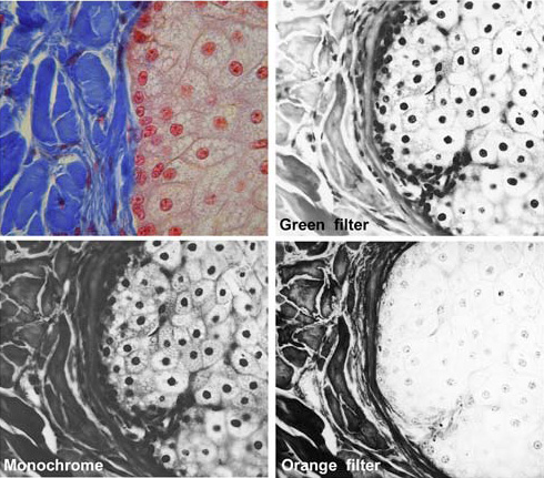
Figure 3. The effect of coloured filters on the image. A filter will transmit light of its own colour and block light from the rest of the spectrum to varying degrees: the complementary colour will be blocked entirely.
Top left: A section of tissue, transmitted-light bright field. The connective tissue, to the left of the image, is stained blue, and the nuclei to the right stained red.
Top right: Viewed with a green filter, recorded in monochrome. The nuclei appear black, whilst the blue connective tissue is reduced in contrast.
Bottom left: Monochrome rendition of the coloured image without filters.
Bottom right: Viewed with an orange filter, the nuclei exhibit reduced contrast, whilst the connective tissue appears much darker.
The green filter is very approximately complementary to red, and the orange filter likewise complementary to blue. Strictly, red, green and blue are the additive primary colours of visible light, with cyan, magenta and yellow respectively complementary to these three primary colours. Cyan, magenta and yellow form the primary colours of the subtractive system used in printing.
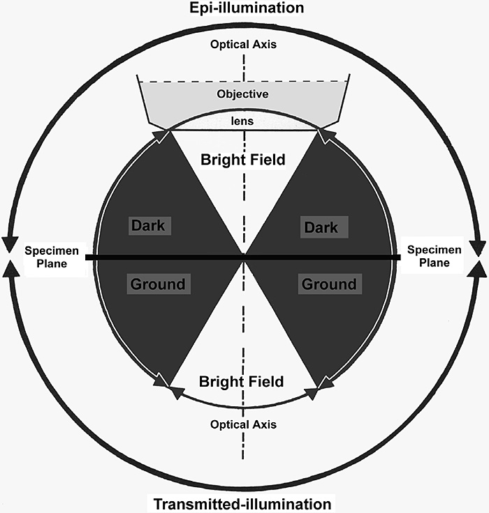
Figure 4. Schematic diagram to show the interconnection between bright-field, oblique and dark-ground illumination using both transmitted and reflected light.
Light falling onto the specimen from above the specimen plane is termed epi-illumination, and the image is formed from light reflected off the top surface of the specimen. Light shone from below passes through the (necessarily thin) specimen, and is termed transmitted-light illumination. If the light falls within the shaded area, outside the acceptance angle of the objective, a dark-ground image will result. (Adapted from Bradbury & Evennett (1994) Contrast Techniques in Light Microscopy [reference 4], with permission).
Digital manipulation of contrast
There are two major ways in which a digital microscopical image may be collected before manipulating the contrast. Firstly, a CCD can be coupled directly to the microscope. Alternatively, a camera is used to take a conventional photograph which is then digitised by scanning the negative, print or slide. The best way of retaining the greatest resolution of detail in the image, is to photograph an image onto slide film, and scan the positive image into digital form using a slide scanner. The information in a digitised image is encoded as a sequence of numbers, using 1 or 0 in binary code, which is unique for each different image. Because computers can process these vast number sequences extremely rapidly, it becomes possible to display images in electronic form quickly and conveniently, and to alter their contrast.
References
I have quoted as few references as possible, but one source [4] on the subject of contrast has been invaluable to me since its publication, and I recommend it to all who seek to understand and manipulate contrast in the microscopical image.
[1] Inoué, S. (1986) Video Microscopy, Plenum Press, New York
[2] Bracegirdle, B. (1993) Beginning with camera and microscope. Quekett Journal of Microscopy 37/1:22-29.
[3] Bracegirdle, B. (1994) Beginning with camera and microscope (2): Choice of films. Quekett Journal of Microscopy 37/3:207-212.
[4] Bradbury, S. & Evennett, P. J. (1996) Contrast Techniques in Light Microscopy, Bios Scientific Publishers, Oxford.
© Jeremy Sanderson, Oxford, 2000