

6. Condensers and contrast
The condenser – different types. Contrast in the microscope
In the previous article on the eyepiece, I pointed out that the eyepiece was normally located so that its front focal plane was co-incident with the Primary Image Plane (PIP). The PIP is conjugate with the specimen in the imaging set of conjugate planes, and so is useful for measuring features of microscopical specimens.
In the same way, the front focal plane of the condenser is conjugate with the back focal plane of the objective (but not the specimen) in the illumination train of rays. The condenser, therefore, provides an accessible place where we may alter or regulate the contrast of the image by manipulating the illuminating rays of light. These two principles arise from Köhler’s method of illumination, which was dealt with in part 3 of this series.
The function of the condenser
The condenser fulfills two functions in the microscope. It provides an area of evenly-illuminated light in the field of view at the specimen plane and illuminates the aperture of the objective uniformly with light of sufficient yet controllable angle. Secondly, as mentioned above, it provides a means of regulating contrast (Bradbury & Evennett, 1996). The simplest form of condenser is the concave mirror, but this is not useful for objectives above NA 0.2 or so. If your microscope has a mirror and a remote light source, the flat side of the mirror must be used in conjunction with any substage condenser fitted. This is because, strictly speaking, the condenser should receive parallel illumination and thus bring this light to a focus at the back focal plane of the condenser (where the specimen is situated).
Types of condenser
The most widely-used type of condenser is the Abbe condenser for bright field microscopy (Figure 1a, 1b). It is constructed of two or three lenses, and the upper short-focus lens can usually be flipped out of the optical path (1a), or unscrewed (1b), in order to fill the field of view with low power objectives. This simple illuminator will suffice for most types of microscopy. It was originally designed to provide narrow beams (or ‘pencils’) of oblique light from an eccentrically-placed aperture in the front focal plane of the condenser. Figure 1c shows a simple two-lens Abbe illuminator mounted on a substage apparatus which could be rotated and moved eccentrically to provide oblique illumination. Figure 1d shows a low-power condenser designed to completely fill the large field of view of very low magnification objectives.
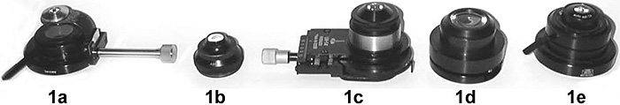
Although a numerical aperture may be quoted for the condenser (often 0.9 NA for dry condensers and 1.4 NA maximum for oil-immersion types), these figures give no indication of the NA for which the illuminating rays are corrected for spherical aberration. In many simple condensers a solid cone of light for axial illumination is seldom corrected for spherical aberration above 0.45 NA. For high quality work, and for resolving structure at the limit of resolution, condensers must be corrected for aberrations. Fully corrected condensers, like objectives, contain many lens elements and can be corrected almost to the same degree. The achromatic-aplanatic condenser (1e) is corrected for both spherical and chromatic aberration, and should be used for the highest quality work, and colour photomicrography. Aplanatic condensers are corrected for spherical aberration only.
So-called ‘universal’ condensers (Figure 2) are multi-functional. They consist of a revolving disk holding a selection of aperture diaphragms, filters, patch stops, phase plates or Wollaston prisms for differential interference contrast (DIC). This arrangement permits changing from one contrast method to another conveniently and easily. The dark-ground patch stop will generally only work up to NA 0.5 or thereabouts. For use with objectives of higher NA, a specially-constructed dark-ground condenser (Figure 3) must be used. For details of its use, and other contrast-enhancement methods, see Bradbury & Evennett (1996).
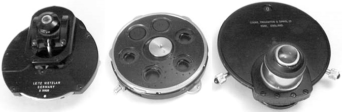
Figure 2. Universal condensers. The central image shows the top cover removed, displaying the revolving disc where the aperture phase annuli, DIC prisms, dark-ground patch stops, Rheinberg discs and Hoffman modulation filters are located. Most universal condensers possess an aperture iris for bright field work, several annuli for phase contrast and a dark-ground stop for low-power dark-ground.
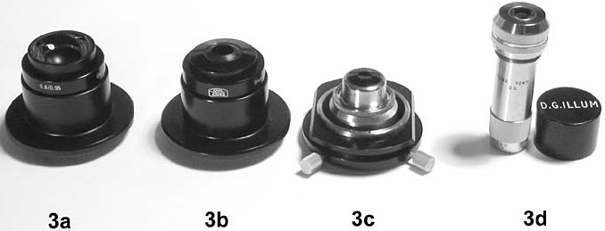
Figure 3. Dark-ground condensers. 3(a) Dry dark-ground condenser. 3(b) & 3(c) Oil-immersion dark-ground condensers. 3(d) Adjustable oil-immersion dark-ground condenser; this condenser can be adjusted to suit different thickness of slide, to give a high quality dark-ground image.
Transmitted and reflected light microscopy
The arrangement of the transmitted-light microscope demands a separate condenser, since the light is first condensed onto the specimen (wherein the light interacts with matter), and is then collected by the objective further along the optical axis.
The situation in the reflected-light microscope is different. Here, the ray path is folded about the axis of the specimen where light is reflected from its surface. The objective acts as its own condenser, and the alignment of the reflected-light microscope is very much simplified (see the ray diagrams in part 2 of this series). However, it is difficult to access the back focal plane of the objective (front focal plane when used as a condenser), so supplementary lenses are used to create a position whereby the image of diaphragms and filters are conjugate with the back focal plane.
The incident-light system is very useful for fluorescence microscopy, chiefly because illumination of the specimen is simple, it is more efficient (giving brighter images at high magnifications) and combination with other contrast methods by transmitted-light is permitted.
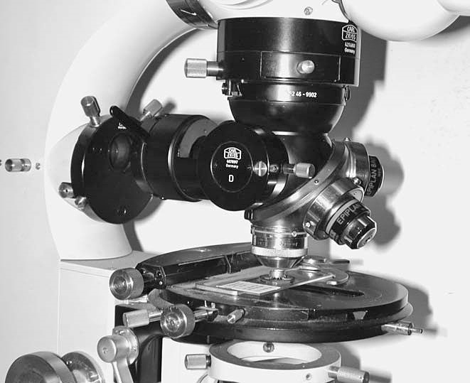
Figure 4. Illustration of an epi-illuminator for reflected-light microscopy
This epi-condenser has two types of reflected-light objectives fitted into its nosepiece. The objective in use is designed for dark-ground illumination, while the other two objectives that can be seen for bright field reflected-light work. The wide collars round these latter two objectives provide for the objective to be centred onto the optical axis. The ‘D’ on the epi-illuminator casing denotes the interchangeable insert that allows the unit to be used for dark-field illumination. It may be exchanged for a plane mirror for bright field reflected-light microscopy. The transmitted-light condenser has been removed from underneath the stage.
If the objective acts as its own condenser in reflected-light microscopy, why are objectives not also used for illumination in transmitted-light microscopy? Apart from the practical difficulty of access to the objective back focal plane, it is difficult to put objectives to multi-function use, and the angle of illumination is not usually controllable (by an iris diaphragm in the objective back focal plane).
Basic principles of contrast enhancement
Sufficient visibility, or contrast, is required for us to perceive the detail in the image that is resolved by our microscopes. Selectivity is important: we need at least some regional differences within the object, and between the object and background, to discern detail.
Contrast in the image is derived by three means, either separately or in combination. They are:
- specimen-light interaction,
- manipulation of the illumination, and
- manipulation of the image-recording medium.
Altering contrast in part (c) can be achieved by photographic development and/or printing, and also using electronic contrast of analogue video or digital images. However, the condenser is instrumental in parts (a) and (b) for manipulating contrast and visibility in the image. Further details of the theoretical and practical aspects of contrast techniques in light microscopy may be found in Bradbury & Evennett, 1996 and Sanderson, 2002, 2000, 1998 and 1994. Briefly, the best-known forms of contrast generation are bright field, oblique illumination, dark-ground & Rheinberg, phase contrast and DIC. It is also possible to combine these methods with different forms of illumination (e.g. polarised light with Rheinberg, or phase contrast by transmitted bright field with incident fluorescence). Since contrast enhancement is very much under the control of the microscopist, the importance of the proper use of the condenser cannot be over-emphasised.
The condenser has to be focused properly (see part 3, setting up the microscope for Köhler illumination) in order to achieve the best quality image. This is true whatever method of contrast enhancement (bright field, phase, dark-ground) is used. The most obvious effect of a de-focused condenser in bright field microscopy is a significant loss of resolving power giving, in turn, a ‘rotten’ image with diffraction haloes around each point in the image. The same result occurs if the top (short-focus) lens is omitted or left flipped-out when a high power objective is used, and the back focal plane of the objective is not completely filled with light.
When phase contrast microscopy is attempted with a wrongly-focused condenser, the annulus in the condenser often will not match the diameter of the phase ring in the back focal plane of the objective, and any contrast enhancement is lost. Problems in focusing the condenser can also result in poor dark-ground microscopy also, if the image of the patch stop does not completely occlude direct illumination from the objective. The next part in this series returns to the objective, and considers tube length, and how to determine the focal length, magnification, aperture and other parameters of your objectives.
References
Bradbury S. & Evennett P. J. (1996) Contrast Techniques in Light Microscopy. Bios Scientific Publishers. ISBN 1-85996-085-5
Sanderson, J. B. (1994) Contrast in Light Microscopy: An Overview. Proceedings of the Royal Microscopical Society 29/4:263-270
Sanderson, J. B. (1998) Contrast Enhancement Techniques for Light Microscopy in Cell Biology: A Laboratory Handbook 2nd Edn. Cellis, J. (ed). (1998) Vol 3: 15–33, Academic Press. ISBN (4-vol set) 0-12-164725-0; vol 3 only = 0-12-164728-5
Sanderson, J. B. (2000) The Theory of Contrast Control in the Microscope, Quekett Journal of Microscopy, 38:617–627.
Sanderson, J. B. (2002) Practical Control of Contrast in the Microscope, Quekett Journal of Microscopy, 39:275–288.
© Jeremy Sanderson, Oxford, 2010