

Taylor water and sediment sampler
By Howard (Chico) Taylor
General description
 My sampler is designed for taking discrete samples at any depth for qualitative and quantitative study, and at the bottom of lakes and rivers where sediments can be collected for sampling interstitial habitats for qualitative study. The unit, with a one litre capacity, has a 60 mm opening at the bottom linked to an air valve at the top. It is water and air tight when these openings are closed. For sampling at moderate depths, the unit is lowered by means of one or more 150 cm sections of ½ in PVC pipe. They assemble to each other and attach to the sampler by means of threaded ends. The number of sections is determined by the depth at which the sample is to be taken. For sampling at depths greater than practical with the pipe sections, the top of the unit is fitted with a weighted section and lowered on a line.
The plate which closes the intake opening at the bottom of the unit is normally held closed by a compression spring, and is linked by a shaft to a ball which seats in a rubber grommet to form the airtight valve. The ball can be adjusted vertically to provide the proper seal when the unit is closed. The upper end of the linking shaft ends in a fitting with a ring for attaching the control line with a snap fitting. When the sampler is lowered to a selected depth or to the bottom and held in place by the extension sections or the weight, tension on the control line opens the intake and the air valve simultaneously. Contained air escapes, allowing water to flow in. Figure 1 illustrates the design principle of the sampler.
Figure 2 shows the unit. The top plate is secured by wing nuts. When these are removed, the interior parts can be lifted out giving access to all parts so the unit can be cleaned. The bottom plate is secured in the same manner.
Design concept
The design makes maximum use of low cost, commercially available parts which require a minimum of machining. These include small plumbing PVC fittings which do not require modification; plumbing PVC pipe, which only requires cutting to length; one larger PVC part which is used for the body and only requires drilling and tapping; brass sheet which requires sawing and drilling; round brass bar and telescoping brass tubing which only require cutting to length; a compression spring, automotive gasket material; threaded brass rod; fasteners; one grommet; two O-rings; one 17 mm diameter bead (such as plastic costume jewelry); one key ring; and four 16 ounce lead sinkers.
| The sampler is shown full size and in partial section in Figure 1. The parts are identified by reference numbers and described in the following notes.
The PVC pipe and the fittings are available from plumbing supply houses and Home Depot in the U.S. They are defined by their interior diameters and types. The outside diameters and lengths of PVC fittings vary somewhat depending on the manufacturer, but this does not present a problem in the the design of this unit. The metal parts are available from Small Parts, Inc., 13980 N. W. 58th Court, P.O.Box 4650, Miami Lakes, Florida 33014-0650, USA. The firm has a website: www.smallparts.com and can be reached by e-mail at [email protected]. SP part numbers are included in the following descriptions. Part NumbersThe original article included SP part numbers from Small Parts Inc., which is now part of Amazon Supply (www.amazonsupply.com). The original part numbers (e.g. SP# O-TTRB-17) have been updated (e.g. (AS# TTRB-17) |
 |
Fabricating details
1 UPPER MALE ADAPTOR – ½ inch PVC, male thread
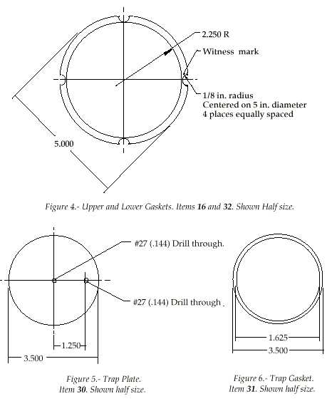
2 SEAL – ½ inch diameter. Can be of any material. It is epoxied into place as shown in figure 2 before part 3 is installed.
3 UPPER LINER ASSEMBLY – Two lengths of brass telescoping tubing:
Material: (A) AS# TTRB-17
Material: (B) AS# TTRB-18
The length of this assembly is not critical. It must fit freely within the assembled parts 1, 4 and 5 and should be shorter than the interior of the assembled PVC parts. The function of the liner is to restrain lateral movement of shaft 36 when the sampler is opened by the off-center control rod 10 so that parallelism between the trap 30 and the opening in the lower plate 32 is maintained. The tubes should be cut so that they will be flush with pipe 4 when it is cemented in place.
4 PIPE – ½ inch PVC. Is installed in part 1 with PVC cement. The length of this part is not critical. The way it assembles in male adaptors 1 and 5 will determine the length of the upper liner assembly 3.
5 LOWER MALE ADAPTOR – ½ inch PVC, male thread. This part is installed and cemented on pipe 4 with the upper liner assembly 3 in place.
6 RING, CONTROL LINE ATTACHING – This can be a key ring. It should be large enough so that a finger can be inserted to open the unit.
| 7 FITTING, RING ATTACHING – AS# S6-12 8 LOCK WASHER – AS# LWX-6 9 NUT – AS# HNX-632 10 CONTROL ROD – AS# TRBB-632 11 FITTING, VALVE SETTING – AS# S6-12 12 LOCK WASHER – AS# LWX-6 13 AIR VALVE – spherical, plastic. See figure 9 14 WING NUT – AS# PWNX-632 |
 |
| 15 UPPER PLATE – Material: AS# SMB-062-c. See Figure 3 16 UPPER GASKET – Victor Gasket. See Figure 4 17 BODY – 4 inch PVC, coupling. See figure 2 18 GROMMET 19 AIR VALVE CENTERING ELEMENT – AS# S6-12 20 LOCK WASHER – AS# LWX-6 21 NUT – AS# HNX-632 22 FEMALE ADAPTOR – ½ inch PVC, female thread 23 LOWER LINER ASSEMBLY – Two lengths of brass telescoping tubing: Material: (A) AS# TTRB-17 Material: (B) AS# TTRB-18 The length of this assembly is not critical, but it must be 3/8 inch shorter than the dimension from the lower male adaptor 5 to the lower end of 24 24 CLOSURE SETTING ELEMENT – Pipe, ½ inch PVC. Is installed in part 22 with PVC cement. The length of this part is determined by the compression spring 27 25 WASHER – AS# WN-1/2 26 OPENING LIMITING ELEMENT – Material: AS# TTRB-17 27 COMPRESSION SPRING – stainless steel, 2 inch free length, 1/16 inch diameter wire, minimum 2½ lbs load when the sampler is closed, 5 lbs load when the trap plate is raised ¼ inch 28 NUT – AS# HNX-632 29 LOCK WASHER – AS# LWX-6 30 TRAP PLATE – Material: AS# SMB-062-c. See Figure 5 31 TRAP GASKET – Victor Gasket. See Figure 6 32 LOWER GASKET – Victor Gasket. See Figure 4 33 LOWER PLATE – Material: AS# SMB-062-c. See Figure 5 34 CONTROL ROD STABILIZER – AS# S6-12 35 LOCK WASHER – AS# LWX-6 36 NUT – AS# HNX-632 37 SHAFT – Material: AS# ZRB-8, Length is not critical, but should be ½ inch shorter than the dimension from seal 2 to trap plate 30 38 LOCK WASHER – AS# LWX-6 39 NUT – AS# HNX-632 40 STUD – Material: AS# TRBB-632, #6-32 threaded rod, brass, 7/8 inch long 41 UPPER O-RING SEAL – AS# ORB-117 42 LOWER O-RING SEAL – AS# ORB-117 |
  |
Sampler parts list
| REF. NO., QUANTITY, DESCRIPTION 1 2 PVC male adaptor, ½ inch 2 1 Disk, ½ inch diameter, any material 3, 23, 26 1 AS# TTRB-17, 9/16 outside diameter 3, 23, 26 1 AS# TTRB-18, 19/32 outside diameter 4, 24 1 PVC pipe, ½ inch, 3 inches long 6 1 Ring, key chain, 1-1/8 maximum diameter 7, 11, 19, 34 4 AS# S6-12, standoff, aluminum, anodized, #6-32 thread, ¾ inch long 8, 12, 20, 29, 6 AS# LWX-6, washer-lock, stainless steel, 35, 38 split type, #6 9, 21, 28, 36 4 AS# HNX-632, nut, #6-32, stainless steel 10, 40 1 AS# TRBB-632, threaded rod, #6-32, brass, 12 inches long 13 1 Bead, spherical, 11/16 diameter, any material 14 8 AS# PWNX-632, wing nut, #6-32, stainless steel 15, 30, 33 1 AS# SMB-062-c, brass sheet, half hard, 1/16 thick, 6×12 inches 16, 31, 32 1 Automotive gasket, 1/32 thick, #JV1 Victor gasket by Dana Corp. Or comparable 17 1 PVC coupling, 4 inch 18 1 Grommet, 3/8 inch interior diameter, for 1/16 inch plate 22 1 PVC female adaptor, ½ inch 25 1 AS# WN-1/2. Flat washer, Nylon 27 1 Compression spring, stainless steel, 19/32 inch inside diameter, 2 inch free length, 2.5 lbs load at closure, 5 lbs compressed ¼ inch to open 37 1 AS# ZRB-8-12, brass rod, ½ inch diameter, 12 inches long 41, 42 2 AS# ORB-117, O-Ring, Buna-N, 13/16 interior diameter, 3/32 wide 1 PVC Cement |
|
 |
 |
Rod and extensions
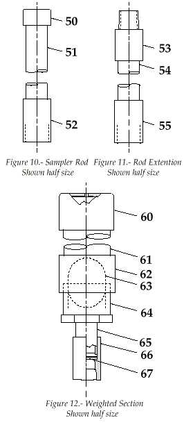
The 150 cm long Sampler Rod shown in Figure 10 threads onto the male fitting 1 shown in figure 1 for collecting bottom samples in shallow water at the shore line. One or more 150 cm long Rod extensions shown in figure 11 can be installed between the rod and the sampler for working in greater depths.
Weighted section
The Weighted Section shown in Figure 12 is loaded with five 16 ounce lead fishing weights. The length of the 1½ inch pipe 61 is determined by the type of weights.
During assembly, the fastener 74 is epoxied into the #27 (.144) clearance drill hole in the cap 60 to make the opening water tight.Seal 67 is epoxied in fitting 66 before pipe 65 is installed.
50
51
52
53
54
55
60
Rod and extensions50 CAP – ½ inch PVC Weighted section60 CAP – ½ inch PVC |
Rod and extensions parts listRef. no., quantity, description50 1 PVC cap, ½ inch Weighted section parts listRef. no., quantity, description60 1 PVC cap, 1½ inch |