

Magic of polarised light
![]()
By Don Thomson
When ordinary light is passed through a polariser, the emerging light has its electric vector confined to a single plane, the permitted vibration direction of the polariser. The most commonly used polarisers are made of plastic sheet, invented by E. H. Land in 1929, and marketed under the name Polaroid. Land later invented a range of instant photography systems using the same trade name. Prior to the invention of Polaroid sheet, Nicol prisms made of Iceland Spar were the most used polarisers in optical instruments, e.g. microscopes, polarimeters etc.
Plane polarised light can only be identified by passing it through a second polariser, distinguished from the first by being called the analyser. On rotation of the analyser, two positions will be found, 180° apart, where the transmission of light is minimal, ideally zero. In this condition the permitted vibration directions of the polariser and analyser are at right angles to each other and the polarisers are said to be crossed.
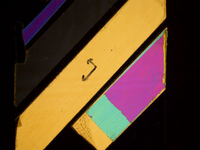 Figure 1
Fig 1 shows a piece of glass, carrying strips of transparent, colourless plastic adhesive tape (Sellotape), at an angle of 45° to the edges of the glass, between crossed polarisers, on a light box. The supporting glass is not visible, while the plastic tapes show bright colours against the dark background. The specimen where there are overlapping layers of tape show different colours, in areas of different thickness. This shows that the plastic materials of which the tapes are made are doubly refracting, that is the refractive index, measured along the length of the sample, has a different value from that measured across the width.
In the case of the supporting glass, the refractive index is the same in all directions, it is said to be optically isotropic, and is not visible under these conditions. The orientation of the polariser is such that the permitted vibration direction is east-west, while that of the analyser is north-south, just the same as those in a polarising microscope. This image therefore mimics that seen with a polarising microscope, viewing narrow straight crystals, or fibres, which are doubly refracting, between crossed polarisers. The specimens need to be orientated at 45° to the permitted vibration directions of the polariser and analyser to show maximum colour, this is why polarising microscopes have rotating stages.
The polarisation colour is produced by interference. Plane polarised light, passing through a doubly refracting material, at 45 degrees to the plane of polarisation, is split into two components, plane polarised at right angles to each other, one parallel to the length of the tape, and the other across the width. This is indicated by the two arrows on the yellow specimen. These two beams of light travel up through the thickness of the specimen at different speeds because of the differing values of refractive index in the two directions of polarisation, so on leaving the specimen, one beam is retarded with respect to the other. The amount of this retardation depends on (1) the difference in the two values of refractive index, this is the birefringence of the material, and (2) the thickness of the specimen. The greater the thickness the greater the retardation. When the two beams of light leaving the specimen hit the analyser, a component of each, in the north-south direction, is transmitted, and interference takes place between the two.
The interference is destructive for that wavelength of light which is equal to the retardation between the two beams. So the yellow specimen in the image has a retardation equal to the wavelength of blue light, between the two beams. Yes, I know that there has to be an odd number of half wavelengths phase difference to give destructive interference, the other half wavelength happens in the analyser. Trust me. A special case of this is an accessory which is widely used in polarised light microscopy, which is a birefringent plate having a retardation of 560 nanometres, the wavelength of green light, known as a first order red plate, which is a pity as the colour produced by removing the green component from white light is in fact magenta, and this is the colour produced in the microscope. In more poetic days it was called a “Sensitive Tint” plate. In use the sensitive tint plate is fitted into a slot provided for the purpose in the polarising microscope, so that the specimen is now viewed against a magenta background. Under these conditions, specimens of low birefringence that appear as dim grey objects against the black background of crossed polarisers, now appear in brilliant blue and yellow against the magenta background, depending on orientation.
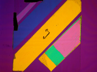 Figure 2
Fig 2 shows the same specimen of plastic tapes between crossed polarisers, but now with a first order red plate, hence the magenta background. Note that the low birefringent specimen, top left, barely visible in Fig 1, now stands out in deep blue.
The effect of rotating the specimen through 90° is shown in Fig 3, in this case a less dramatic image.
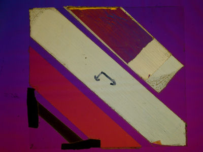 Figure 3
Nineteenth century microscopes frequently had a number of retardation plates, called Selenites, as they were made from this naturally occurring form of calcium sulphate. These were often fitted in sets of three, each in its own rotating mount, to be swung into a space in the condenser barrel above the Nicol prism polariser. Using these a very wide range of background colour effects can be produced, but it is difficult to reproduce any previous setting.
Real retardation plates are very expensive so this is a good field for improvisation using plastic film of various kinds from packaging material and the like, a good excuse to buy expensive boxes of chocolates etc. Transparent adhesive tape (such as Sellotape, or the thin material covering new CDs – AW) stuck on microscope slides can be used, one just has to search for materials which give a good saturated colour between crossed polarisers. Try using various thicknesses by laminating two or more layers, so long as any mountant used for the purpose does not dissolve the plastic In use these home made devices need to be fitted between the polariser and the condenser, the optical properties are unlikely to be good enough to use in the image forming optics like the real ones, but this does not matter. There have been many books written on this subject, most of which would provide light reading for Albert Einstein but are too deep for me.
One of the early Presidents of the Royal Microscopical Society used to keep slides in what he called his “Goodness Gracious Box”, polarised light does this rather well, and the science is all there in books for those who want it.